Download
1 / 23
230 likes | 240 Views
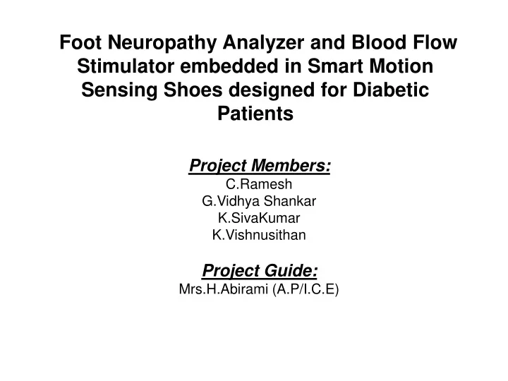
Foot Neuropathy Analyzer and Blood Flow Stimulator embedded in Smart Motion Sensing Shoes designed for Diabetic Patients. Project Members: C.Ramesh G.Vidhya Shankar K.SivaKumar K.Vishnusithan Project Guide: Mrs.H.Abirami (A.P/I.C.E). ABSTRACT:.

E N D
Foot Neuropathy Analyzer and Blood Flow Stimulator embedded in Smart Motion Sensing Shoes designed for Diabetic Patients Project Members: C.Ramesh G.Vidhya Shankar K.SivaKumar K.Vishnusithan Project Guide: Mrs.H.Abirami (A.P/I.C.E)
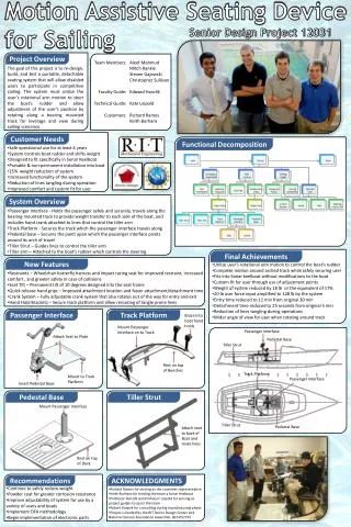
ABSTRACT: • Our project is to design and build a low-cost foot pressure and foot movement analysis and blood flow stimulation system, embedded within smart footwear which a patient can wear at any place to monitor his or her foot pressure distribution to identify and diagnose foot neuropathy as early as possible.
EXISTING SOLUTION: • Diabetic Neuropathy is a serious medical disorder and can be prevented by the early detection of abnormal pressure patterns under the foot. • Although equipment to measure foot pressure distribution is available in India and elsewhere, these are still not readily accessible for a large segment of the population, are too expensive to own, and are too bulky to be portable. • The foot pressure monitors are also not readily available in less developed countries which are home to many communities with a high prevalence of diabetes.
DISADVANTAGE OF EXISTING METHOD: • There are no possible method to identify or prevent this serious disorder. • The only way is the removal of the infected part.
ADVANTAGE OF PROPOSED METHOD: • This project not only enables early detection but also provides treatment and prevention of Diabetic Neuropathy which is a serious medical disorder • Equipment to measure foot pressure distribution is neither too expensive to own or too bulky to be portable. • The system design in our project is such that the sensors and actuators can be fitted within the shoe unit and the monitoring unit a simple handheld device allowing to overcome the previous drawback. • Thus our project will be cheaper and readily available in less developed countries which are home to many communities with a high prevalence of diabetes.
ADVANTAGE OF PROPOSED METHOD: • Large external memory allows the system to continuously store data from the smart shoe even for several weeks. • Advanced Color Graphical User Interface with the help of a TFT LCD and Touchscreen Panel. • Next generation ARM Cortex-M3 (LPC1313)architecture is the chosen hardware platform, ideal when low power and high performance is needed.
Block diagram:Hand Held Unit SPI GPIO GPIO UART
Block diagram:Smart Wear Unit UART PWM ADC I2C
Hardware Used: • Flexi Flow Sensor • LPC1313 Micro controller • MEMS Accelerometer • MiWi IEEE 802.15.4 Protocol • Vibration Motor • SD Memory Card • Colour TFT LCD Display
Software Libraries Used: • C Programming Language • Flash Magic Software
Circuit Diagram: • In this circuit LPC1313 (32 bit) micro controller hich is based on ARM Cortex-M3 which is a next generation core that offers system enhancements. • Both the footwear unit and the handheld display unit use LPC1313, a 32-bit ARM Cortex-M3 Microcontroller from NxP Semiconductors. • The pin 5, 41 is connected to a voltage source of 2.0V to 3.6V.The pins 6 and 7 are connected to the oscillator input and oscillator output respectively. • The oscillator is of 12MHz frequency and is used to produce clock signals. The pins 8, 44 are connected to Vdd 3.3V supply voltage to the internal regulator and the ADC. • A buzzer or beeper is audio signaling device, which may be mechanical, electromechanical, or piezoelectric.
Pin 46 and 47 are connected to the MiWi device for receiving and transmission purposes. • These are connected to pin 7 and 5 in MiWi for the same receiving and transmitting respectively. The pins P2_4 to pin P2_11 are General Purpose registers used as the Digital input/output pins. • DB to DB7 is the 8 bit data lines which carry Data from one device to another device. • The microcontroller also runs software such as a Graphics Library, a FAT-32 File System and an IEEE 802.15.4 Wireless Networking Protocol Stack.
HARDWARE DESCRIPTION: LPC1313 Micro controller • The LPC1313 are ARM Cortex-M3 based microcontrollers. • It is used for embedded applications featuring a high level of integration and low power consumption of about 3.2V. • The ARM Cortex-M3 is a next generation core that offers system enhancements such as enhanced debug features and a higher level of support block integration. • In this project this micor controller is use in both the units(Hand Held and Foot Wear units). • It is also used in reducing code size and more battery life.
Flexi force sensor: • A force-sensitive resistor has a variable resistance as a function of applied pressure. • It is also knownas “pressure-sensitive”, since the sensor's output is dependent on the area on the sensor's surface to which force is applied. • When external force is applied to the sensor, the resistive element is deformed against the substrate. • Air from the opening is pushed through the air vent in the tail, and the conductive material on the substrate comes into contact with parts of the active area. • The more of the active area that touches the conductive element, the lower the resistance.It is similar to a strain Gauge.
MEMS Accelerometer: • Micro-Electro-Mechanical Systemsis a technology that in its most general form can be defined as miniaturized mechanical and electro-mechanical elementsthat are made using the techniques of microfabrication. • The LIS302DL is an ultra compact low-power three axes linear accelerometer. • It includes a sensing element and an IC interface able to provide the measured acceleration to the external world through I2C/SPI serial interface. • it is capable of measuring accelerations with an output data rate of 100 Hz or 400 Hz. • When an acceleration is applied to the sensor the proof mass displaces from its nominal position, causing an imbalance in the capacitive half-bridge. This imbalance is measured using charge integration in response to a voltage pulse applied to the sense capacitor.
MIWI P2P WIRELESS PROTOCOL: • The Microchip MiWi P2P Wireless Protocol is a variation of IEEE 802.15.4, using Microchip’s MRF24J40MA 2.4 GHz transceiver and any Microchip 8, 16 or 32-bit microcontroller with a Inter Integrated Circuit (I2C). • The protocol provides reliable direct wireless communication via an easy-to-use programming interface. • Designed only for low-data rates and being low-cost, it has an integrated PCB antenna. • It would save money for small and medium project designers, by eliminating the need to receive independent FCC certification for their wireless products.
SD Memory card: • Secure Digital is a non-volatile memory card format for use in portable devices, such as mobile phones, GPS navigation devices, and tablet computers. • Electrically passive adapters allow the use of a smaller card in a host device built to hold a larger card. • It defined an SDIO card family that provides input-output functions and may also provide memory functions. These cards are only fully functional in host devices designed to support their input-output functions.
Resistive touch screen: • A resistive touch screen works by applying a voltage across a resistor network and measuring the change in resistance at a given point on the matrix where a screen is touched by an input stylus, pen, or finger. • The change in the resistance ratio marks the location on the touch screen. • The device requires an external reference and an external clock. It operates from a single supply of 2.7V to 5.25V.
Vibrating Motor: • A vibrating alert is a feature of communications devices to notify the user of an incoming connection. • A vibrator is a mechanical device to generate vibrations. The vibration is often generated by an electric motor with an unbalanced mass on its driveshaft. • There are many different types of vibrator. Some are components of larger products such as cellphones, pagers.
Software Description: FLASH MAGIC: • Flash Magic is Windows software that allows easy access to all the Internet Service Provider features provided by the devices. • Flash Magic provides a clear and simple user interface to the features. • The codes are converted into Hex file by loading the codes in the software. • If there are any Hex file loaded previously,then it can be erased.Then it is possible to run the Hex file and the codes are uploaded to Micro controller and then executed.
Conclusion: • This project has a great advantage in the bio medical field in the observation and treatment of the diabetic patients. • They are easily liable in the Parkinson’s disease which makes the sugar patients a paralytic person. • This Parkinson’s disease starts in the body part with which one works with pressure. • That is probably the feet, because while walking pressure is applied on our feet. • Hence this project is mainly focused on the sensors embed in wearable shoes which is easy to measure while wearing it.
Reference: • Monitoring of Posture Allocations and Activities by a Shoe-Based Wearable Sensor Edward S. Sazonov*, Member, IEEE, George Fulk, James Hill, Yves Schutz, and Raymond Browning April 15 2010. • Human Gait Modeling Using a Genetic Fuzzy Finite State MachineAlberto Alvarez-Alvarez, Student Member, IEEE, Gracian Trivino, Member, IEEE, and Oscar Cord´on, Senior Member, IEEE April 03 2012 • On-Shoe Wearable Sensors for Gait and TurningAssessment of Patients with Parkinson’s Disease Benoit Mariani, Mayt ´ e Castro Jim´enez, Franc¸ois J. G. Vingerhoets, and Kamiar Aminian, Member, IEEE January 12 2013 • A. D. Macleod and C. E. Counsell, “Timed tests of motor function in Parkinson’s disease,” Parkinsonism Related Disorders, vol. 16, no. 7, pp. 442–446, Aug. 2010. • P.J.M.Havinga, M.MarinPerianu, and J.P.Thalen ,“Sensor Shoe: Mobile gait analysis for Parkinson’s disease patients,” presented at the UbiComp, Innsbruck, Austria, 2007.