Download
1 / 60
600 likes | 603 Views
TIMA/QLF. TIMA Laboratory «Circuit Qualification» group Grenoble - France http://tima.imag.fr. Managing transient effects of radiation on complex microelectronic systems Raoul Velazco and Francisco J. Franco. OUTLINE Motivation A description of SEE’s Sources of SEE’s

E N D
TIMA/QLF TIMA Laboratory «Circuit Qualification» group Grenoble - France http://tima.imag.fr Managing transient effects of radiation on complex microelectronic systems Raoul Velazco and Francisco J. Franco
OUTLINE • Motivation • A description of SEE’s • Sources of SEE’s • Mitigation of SEE’s • Evaluating SEE sensitivity • Conclusions Seminario NICRON, Universidad del Valle, 14 Diciembre 2006
1. Motivations • The microelectronic technology is constantly changing: • higher density, • faster devices, • lower power. • These increase the devices’ vulnerability to the effects of radiation (not only in nuclear- space environments). • In some applications, no failure is allowed. • Future sub-micronic technologies are potentially sensitive to the effects of atmospheric neutrons. Seminario NICRON, Universidad del Valle, 14 Diciembre 2006
T.I.D. Accumulated Displacement Single Particle S. E. E. 2. A Description of SEE’s Radiation and Electronic Devices Seminario NICRON, Universidad del Valle, 14 Diciembre 2006
2. A Description of SEE’s Whatyou always wanted to know about Single Event Effects (SEE’s) • What are they?:One of the result of the interaction between the radiation and the electronic devices • How do they act?: Creating free charge in the silicon bulk that, in practical, behaves as a short-life but intense current pulse • Which are the ultimate consequences? From simple bitflips or noise-like signals until the physical destruction of the device Seminario NICRON, Universidad del Valle, 14 Diciembre 2006
CHARGE COLLECTION VOLUME 2. A Description of SEE’s The Physical Mechanism The incident particle generates a dense track of electron hole pairs and this ionization cause a transient current pulse if the strike occurs near a sensitive volume. Seminario NICRON, Universidad del Valle, 14 Diciembre 2006
2. A Description of SEE’s The Classification of SEE’s SINGLE EVENT UPSET (SEU):CHANGE OF DATA OF MEMORY CELLS MULTIPLE BIT UPSET (MBU):SEVERAL SIMULTANEOUS SEU’S SINGLE EVENT TRANSIENT (SET):PEAKS IN COMBINATIONAL IC’s FUNCTIONAL INTERRUPTION (SEFI):PHENOMENA IN CRITICAL PARTS SINGLE EVENT LATCH-UP (SEL):PARASITIC THYRISTOR TRIGGER AND OTHERS… HARD ERRORS vs SOFT ERRORS Seminario NICRON, Universidad del Valle, 14 Diciembre 2006
2. A Description of SEE’s Some Useful Definitions LINEAR ENERGY TRANSFER (LET) CROSS SECTION (s) SOFT ERROR RATE:PROBABILITY OF AN ERROR AT USUAL CONDITIONS FIT: Typical unit of SER Probability of 1 ERROR every 109 h E.g.- 180-nm SRAM: 1000-3000 FIT/Mb Seminario NICRON, Universidad del Valle, 14 Diciembre 2006
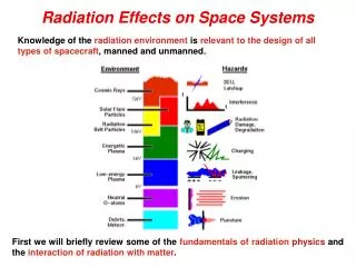
Cosmic rays Protons from solar flares 3. Sources of SEE’s Usually, SEE’s have been associated with space missions because of the absence of the atmospheric shield… • Unfortunately, our quiet oasis seems to be vanishing since the enemy is knocking on the door… • Alpha particle from vestigial U or Th traces • Atmospheric neutrons and other cosmic rays Seminario NICRON, Universidad del Valle, 14 Diciembre 2006
3. Sources of SEE’s Alpha Particles • Sometimes, they appeared without a warning and, after some months and spending a lot of money, the source is detected*. • In 1978, Intel had to stop a factory because water was extracted from a nearby river that, upstream, is too close to an old uranium mine. * J. F. Ziegler and H. Puchner, “SER – History, Trends and Challenges. A guide for Designing with Memory ICs”, Cypress Semiconductor, USA, 2004. Seminario NICRON, Universidad del Valle, 14 Diciembre 2006
3. Sources of SEE’s Alpha Particles • Sometimes, they appeared without a warning and, after some months and spending a lot of money, the source is detected*. • In 1986, IBM detected a high rate of useless devices and related it to the phosphoric acid, the bottles of which were cleaned with a 210P deionizer gadget…hundreds of kms far. * J. F. Ziegler and H. Puchner, “SER – History, Trends and Challenges. A guide for Designing with Memory ICs”, Cypress Semiconductor, USA, 2004. Seminario NICRON, Universidad del Valle, 14 Diciembre 2006
3. Sources of SEE’s Alpha Particles • Sometimes, they appeared without a warning and, after some months and spending a lot of money, the source is detected*. • In 1992, the problem came from the use of bat droppings living in cavern with traces of Th and U to obtain phosphorus. * J. F. Ziegler and H. Puchner, “SER – History, Trends and Challenges. A guide for Designing with Memory ICs”, Cypress Semiconductor, USA, 2004. Seminario NICRON, Universidad del Valle, 14 Diciembre 2006
3. Sources of SEE’s Alpha Particles • But sometimes, we are a little naive… • Solder balls are usually made from Sn and Pb, which come from minerals where there may be uranium and thorium traces. Nevertheless, the designer forget this detail and places the solder balls too close to critical nodes! Seminario NICRON, Universidad del Valle, 14 Diciembre 2006
3. Sources of SEE’s Alpha Particles • Fortunately, they are easily controlled following some simple rules during the manufacturing process. But, sometimes, the enemy strikes back! In 2005, a figure of 2·106 FIT/Mbit was observed in the SRAMs attached to pacemakers where: • the package had been removed by cosmetic reasons • And the solder balls had not been previously purified*. Fortunately, nobody deceased (We cross our fingers). * J. Wilkinson, IEEE Trans. Dev. Mat. Reliab., 5 (3), pp. 428-433, 2005 Seminario NICRON, Universidad del Valle, 14 Diciembre 2006
3. Sources of SEE’s Cosmic Rays Usually, they had been a headache for the designers of electronics boarded in space missions… Here you are some of their practical jokes*… • Cassini Mission (1997).- Some information was lost because of MBUs. • Deep Space 1.- An SEU caused a solar panel to stop opening out. • Mars Odyssey (2001).- Two weeks after the launch, alarms went off because some errors lately attributed to an SEU. • GPS satellite network.- One of the satellites is out of work, probably because of a latch-up. * B. E. Pritchard, IEEE NSREC 2002 Data Workshop Proceedings, pp. 7-17, 2002 Seminario NICRON, Universidad del Valle, 14 Diciembre 2006
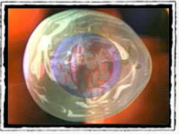
3. Sources of SEE’s Cosmic Rays A nice example… The birth of a star, picture taken by the Hubble Telescope Don’t you realise that there is something odd in the picture? Seminario NICRON, Universidad del Valle, 14 Diciembre 2006
3. Sources of SEE’s Cosmic Rays at Ground Level • The highest fluence is reached between 15-20 km of altitude. • Less than 1% of this particle rain reaches the sea level. • The composition has also changed… • Basically, neutrons and some pions Usually, the neutron flux is referenced to that of New York City, its value been of (in appearance) only 15 n/cm2/h • This value depends on the altitude (approximately, x10 each 3 km until saturation at 15-20 km). • And also on latitude, since the nearer the Poles, the higher rate. • South America Anomaly (SAA), close to Argentina • 1.5 m of concrete reduces the flux to a half. What a weak foe, really should be we afraid of? Seminario NICRON, Universidad del Valle, 14 Diciembre 2006
3. Sources of SEE’s Cosmics Rays at Ground Level Perhaps, we may believe that we are in a safe shelter but… • 1992.- The PERFORM system, used by airplanes to manage the taking-off manoeuvre had to be suddenly replaced because of the SEUs in their SRAMs*. • 1998.- A study reported that, every day, the 1 out of 10000 SRAMs attached to pacemakers underwent bitflips**. This factor being 300 times higher if the patient had taken an transoceanic aircraft. * J. Olsen, IEEE Trans. Nucl. Sci., 1993, 40, 74-77 ** P. D. Bradley, IEEE Trans. Nucl. Sci., 45 (6), 2829-2940 Seminario NICRON, Universidad del Valle, 14 Diciembre 2006
3. Sources of SEE’s Cosmic Rays at Ground Level • The call of the Thousand (2000).- Sun Unix server systems crashed in dozens of places all over the USA because of SEU’s happening in their cache memory, costing several millions of dollars*. • 2005.- After 102 days, the ASC Q Cluster supercomputer showed 7170 errors in its 81-Gb cache memory, 243 of which led to a crash of the programs or the operating system**. * FORBES, 2000 ** K. W. Harris, IEEE Trans. Dev. Mat. Reliab., 2005, 5, 336-342 Seminario NICRON, Universidad del Valle, 14 Diciembre 2006
3. Sources of SEE’s Cosmic Rays at Ground Level • The call of the Thousand (2000).- Sun Unix server systems crashed in dozens of places all over the USA because of SEU’s happening in their cache memory, costing several millions of dollars*. • 2005.- After 102 days, the ASC Q Cluster supercomputer showed 7170 errors in its 81-Gb cache memory, 243 of which led to a crash of the programs or the operating system**. * FORBES, 2000 ** K. W. Harris, IEEE Trans. Dev. Mat. Reliab., 2005, 5, 336-342 Seminario NICRON, Universidad del Valle, 14 Diciembre 2006
ALWAYS DAMNING THE PROGRAM DEVELOPPER? PERHAPS, IT MIGHT HAVE BEEN AN SEU!!! Seminario NICRON, Universidad del Valle, 14 Diciembre 2006
3. Sources of SEE’s Cosmic Rays at Ground Level Why these exotic phenomena are appearing at lower and lower altitude? The present trend is to minimise the typical layout length. This has helped to decrease the sensitive volume but, also, the critical charge does. T. Granlund, IEEE Trans. Nuc. Sci., 2003, 50, 2065-2068 Most pessimistic simulations show a rock-bottom at 130-180 nm and a sudden increase is expected for more advanced technologies. Seminario NICRON, Universidad del Valle, 14 Diciembre 2006
3. Sources of SEE’s Cosmic Rays at Ground Level In any case, everybody agrees with an increasing error rate in the whole system… And with the increasing sensitivity of the combinational logic devices. * R. Baumann, IEEE Trans. Dev. Mat. Reliab., 2005, 5, 305-316 Seminario NICRON, Universidad del Valle, 14 Diciembre 2006
3. Sources of SEE’s Cosmic Rays at Ground Level Can this background be worse? Yes, it can. Some details may increase the neutron sensitivity. • Power supply values.- The lower, the more likely the SEU’s • Frequency of work.- SEU’s are more dangerous while the system is reading or writing. • Presence of Boron.- There is an isotope of boron, 10B, able to trap low energy thermal neutrons and release an energetic alpha particle. • Altitude Seminario NICRON, Universidad del Valle, 14 Diciembre 2006
4. Mitigation of SEE’s First of all, Where must we expect SEEs? • All the combinational stages are supposed to be affected by SETs. • Everything having SRAM cells is a candidate to show SEUs, MBU’s: • SRAM’s, Microprocessors, FPGAs, ASICs, etc. • Other devices seem to be quite SEE-tolerant because of their way of building: • DRAMs, PSRAMs, NAND memories, etc. Which are the strategies to mitigate SEE’s? • Technological • Design • Software and Hardware Redundancy Seminario NICRON, Universidad del Valle, 14 Diciembre 2006
4. Mitigation of SEE’s Technological Strategies • First Option: Removal of widely-used BPSG layer • Used for planarization between metallic layers. • If removed, the chance of SEUs is 8-10 times lower. • The use of PSG process is recomended. • If this removal were not possible, we may minimise the SEU incidence by means of: • Boron purification.-Only 20% of natural boron is 10B, the rest being 11B, insensitive to neutrons. • Cover the IC with a 3-mm B4Si3 layer, which absorbs most neutrons and emits the alpha particles far from the critical nodes. Seminario NICRON, Universidad del Valle, 14 Diciembre 2006
4. Mitigation of SEE’s Technological Strategies • Second Option: Redesign the IC in SOI technology. • SOI technology has a tolerance five times higher than that of same typical length bulk technology. R. Baumann, 2005 NSREC Short Course Seminario NICRON, Universidad del Valle, 14 Diciembre 2006
Solved adding a resistor… With the penalty of increasing the complexity of the device. 4. Mitigation of SEE’s Technological Strategies • Second Option: Redesign the IC in SOI technology. • However, they are susceptible to undergo Single Event Snapback Fortunately, new generation fully depleted SOI devices seems to be 20 times more tolerant than partially depleted ones, without using transistors. Seminario NICRON, Universidad del Valle, 14 Diciembre 2006
Collection Volume (No Buried Impl.) Collection Volume (Buried Impl.) 4. Mitigation of SEE’s Technological Strategies • Third Option: Managing the doping profile. • If SOI technologies are not available, • The doping profile can be modified to create wells • Thus, the charge collection area shrinks. The drawback is that there must be an additional layer as well as an extra thermal cycle… to reduce the sensitivity only to 25-50% Seminario NICRON, Universidad del Valle, 14 Diciembre 2006
Sensitive nodes 4. Mitigation of SEE’s Design Strategies Instead of using typical circuits, let us try to improve them. Example: A SRAM cell Seminario NICRON, Universidad del Valle, 14 Diciembre 2006
4. Mitigation of SEE’s Design Strategies Sometimes, the cell may be hardened adding some resistors. Penalties: Actually, we have added a LP filter Frequency behaviour worsens Seminario NICRON, Universidad del Valle, 14 Diciembre 2006
THE HIT CELL THE DICE CELL 4. Mitigation of SEE’s Design Strategies Or, to feed-back the cell to minimise the action of the single events… Seminario NICRON, Universidad del Valle, 14 Diciembre 2006
4. Mitigation of SEE’s Design Strategies The penalty of this choice is obvious… THE SIZE!!!!! EXAMPLES…. • DICE.- 10 NMOS + 4 PMOS • HIT.- 6 NMOS + 6 PMOS • LIU.- 9 NMOS + 6 PMOS • ROCKET.- 8 NMOS + 8 PMOS • WHITAKER.- 8 NMOS + 8 PMOS And, along with it, the power consumption. Seminario NICRON, Universidad del Valle, 14 Diciembre 2006
4. Mitigation of SEE’s Software and Hardware Redundancy Strategies Your strategies, if you don’t feel like redesigning all your chips. • SIXOPTIONS TO CHOOSE… • Use of Error Correction Codes • Interleaving Bits • Periodical Refresh or Resetting. • Triple Modular Redundancy (TMR) • Time Redundancy • Software Redundancy THEY DO NOT EXCLUDE EACH OTHER! Seminario NICRON, Universidad del Valle, 14 Diciembre 2006
4. Mitigation of SEE’s Software and Hardware Redundancy Strategies Error Correction Codes (ECC-EDAC) Fundamentals: Instead of saving the data as they are, they are stored making use of an error correction code (E. g. Hamming) Advantages • Easy implementation • Able to detect and correct all the SEUs. Drawbacks • The effective memory size decreases. • To codify 64 bits, 8 extra bits are needed. • Cannot correct any sort of MBUs. • They are 2% of typical radiation induced SEUs. • What happens if the coder or the decoder fails? Seminario NICRON, Universidad del Valle, 14 Diciembre 2006
4. Mitigation of SEE’s Software and Hardware Redundancy Strategies Interleaving Bits Fundamentals: MBU’s usually affect adjacent memory cells. Therefore, never should neighbour cells be used. Advantages • Higher MBU tolerance Drawbacks • The effective memory size decreases to a half. • We insist… What happens if the coder or the decoder fails? Seminario NICRON, Universidad del Valle, 14 Diciembre 2006
4. Mitigation of SEE’s Software and Hardware Redundancy Strategies Periodical Refresh and Resetting Fundamentals: In systems with a large amount of FPGA’s or microprocessors, the programs will be periodically reloaded. Advantages • Easy to implement • Easy to maintain and update. Drawbacks • Only for huge systems with a large amount of devices where, in case some of them fails, the whole system does not crash. • Obviously, the backup copy of the program must be radiation-tolerant. Seminario NICRON, Universidad del Valle, 14 Diciembre 2006
A System A B VS INPUT BUS System B VOTING SYSTEM C System C 4. Mitigation of SEE’s Software and Hardware Redundancy Strategies Triple Modular Redundancy (TMR) Fundamentals: Three devices will do the same task and a block selects the most “popular” output. VOTING SYSTEM Seminario NICRON, Universidad del Valle, 14 Diciembre 2006
4. Mitigation of SEE’s VOTER Three Identical devices Software and Hardware Redundancy Strategies Triple Modular Redundancy (TMR) EXAMPLE: A TMR D-FLIP FLOP Seminario NICRON, Universidad del Valle, 14 Diciembre 2006
4. Mitigation of SEE’s Software and Hardware Redundancy Strategies Triple Modularity Redundacy (TMR) Advantages • Easy to implement • Some tools are available for FPGA’s and CPLD’s. Drawbacks • The size of the design is x3 • Sometimes, only some critical blocks should be hardened. • A little decrease in the circuit speed due to the new stage • What happens if the voter fails? • Should we add more and more voter stages? Seminario NICRON, Universidad del Valle, 14 Diciembre 2006
Therefore, if you are an insecure designer… But be careful and do not become a paranoid… 4. Mitigation of SEE’s Software and Hardware Redundancy Strategies Triple Modularity Redundacy (TMR) If we go on, we’ll end up using an FPGA to mimic a flip-flop!!!! Seminario NICRON, Universidad del Valle, 14 Diciembre 2006
4. Mitigation of SEE’s Software and Hardware Redundancy Strategies Time Redundancy Fundamentals: Instead of using three blocks, let us use several times the same system. SOME EXAMPLES… Seminario NICRON, Universidad del Valle, 14 Diciembre 2006
4. Mitigation of SEE’s Software and Hardware Redundancy Strategies Time Redundancy 1.- TMR with delayed inputs • Drawbacks • T > TSE & TCK1 = 4·T Seminario NICRON, Universidad del Valle, 14 Diciembre 2006
4. Mitigation of SEE’s Software and Hardware Redundancy Strategies Time Redundancy 2.- Duplex with delayed comparison • Drawbacks • Frequency Limitations Seminario NICRON, Universidad del Valle, 14 Diciembre 2006
4. Mitigation of SEE’s Software and Hardware Redundancy Strategies Software Redundancy* Fundamentals: Modifications of the program adding check and correction capabilities (duplication of data and instructions, temporal redundancy, etc.) of SEU’s Advantages • It allows to harden any device (From PIC’s to PowerPC’s) • Detects more than 90% of anomalous program behaviour. Drawbacks • The programmation is not so simple. • The size of the program soars up to 3-4 times the original one. * M. Rebaudengo et al. “Coping with SEUs/SETs in microprocessors by means of low-cost solution”, IEEE Trans. Nuc. Sci., 49 (3), 2002, pp. 1491-1495 Seminario NICRON, Universidad del Valle, 14 Diciembre 2006
5. Evaluating SEE sensitivity The devices has been built but… How to determine their sensitivity to SEE’s? There are some ways of finding it out… • Life tests • Accelerated radiation ground tests • Fault injection Seminario NICRON, Universidad del Valle, 14 Diciembre 2006
5. Evaluating SEE sensitivity Life Tests Fundamentals: Gathering a high number of devices to increase the total number of SEE’s, valid statistical results are obtained. Advantages • Devices are tested where they are supposed to work • The only actual and trustworthy results Drawbacks • Large amount of devices (cost, power consumption, facility) • Longtime to obtain good results • Influenced by the aleas of the sun activity Seminario NICRON, Universidad del Valle, 14 Diciembre 2006
5. Evaluating SEE sensitivity Life Tests An example: The Rosetta Project, for Xilinx’ FPGA’s IEEE Trans. Dev. Mat. Reliab. 5 (3), 2005, pp. 317-328 Seminario NICRON, Universidad del Valle, 14 Diciembre 2006
5. Evaluating SEE sensitivity Life Tests Other examples: • MPTB (Microelectronics and Photonics Testbed), on board a satellite from Naval Research Labs (Launched in 1996). • ASTEP (Altitude SEE Test European Platform) • Pic de Bures (2552 m), French Alps • 130 nm & 5 Gb SRAMs 10 SEU/month • Operational since March 2006 • LWS/SET (Living With a Star, Space Environment Testbed), on board a satellite from NASA (GFSC), to be launched in 2008. Seminario NICRON, Universidad del Valle, 14 Diciembre 2006
5. Evaluating SEE sensitivity Accelerated Radiation Ground Tests Fundamentals:The more particles hit the circuits, the more events are recorded. They need: • a particle beam, which can be obtained by Radiation Facilities : • particle accelerators: cyclotrons, linear accelerators,... • equipments based on fission decay sources such as Cf252 • laser beams • test methodology, defining the activity of the device under test (DUT) • an electronic test equipment for controlling and observing the behavior of the DUT during its exposition to radiation. • and.... a deep expertise and ...good luck Seminario NICRON, Universidad del Valle, 14 Diciembre 2006