Download
1 / 53
540 likes | 736 Views
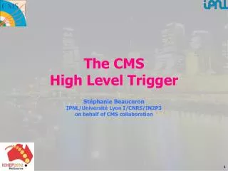
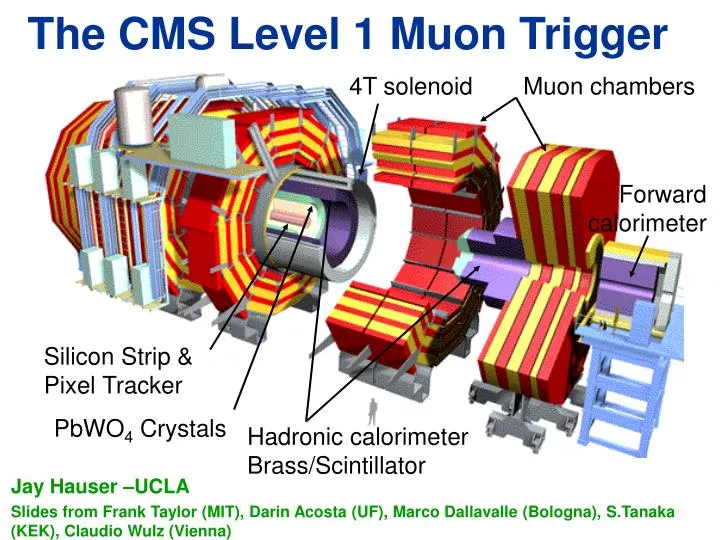
The CMS Level 1 Muon Trigger. Jay Hauser –UCLA Slides from Frank Taylor (MIT), Darin Acosta (UF), Marco Dallavalle (Bologna), S.Tanaka (KEK), Claudio Wulz (Vienna). 4T solenoid. Muon chambers. Forward calorimeter. Silicon Strip & Pixel Tracker. PbWO 4 Crystals.

E N D
The CMS Level 1 Muon Trigger Jay Hauser –UCLA Slides from Frank Taylor (MIT), Darin Acosta (UF), Marco Dallavalle (Bologna), S.Tanaka (KEK), Claudio Wulz (Vienna) 4T solenoid Muon chambers Forward calorimeter Silicon Strip & Pixel Tracker PbWO4 Crystals Hadronic calorimeterBrass/Scintillator
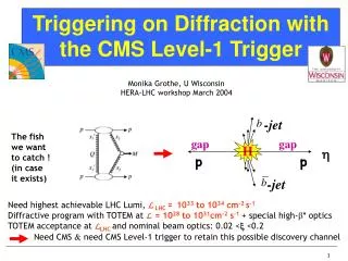
Z′→ee, µµ: CMS Discovery Potential 2 Different models 2 different decay channels Probe new territory in first month (maybe days if lucky!) “1 year” “1 month” “1 day” At canonical LHC luminosity… Tevatron reach The CMS Level 1 Muon Trigger
Level 1 muon trigger • Why high-momentum leptons? • QCD (strong interaction) provides many jets and large energy deposition, but generally not signatures of electroweak processes • So signatures with large energy deposition face large QCD backgrounds • Electrons, muons, taus are signatures of W, Z bosons, top quarks, higgs bosons, SUSY decays, etc., but are rare from QCD. • Muons especially: • Excellent background reduction possible. • Excellent momentum resolution for invariant masses etc. • Muon triggering: • You must catch the fish before you can eat it. • Typical Wmn muon transverse momentum <40 GeV/c. Wish to trigger above 15 or 20 GeV/c, typically. The CMS Level 1 Muon Trigger
Outline • The three types of muon detectors in CMS: • Drift Tubes (DT) • Cathode Strip Chambers (CSC) • Resistive Plate Chambers (RPC) • Overview of triggering at the LHC • Level 1 muon trigger algorithms • Implementation in electronics • Private concerns The CMS Level 1 Muon Trigger
Introduction • All modern collider detectors have these elements covering close to 4p solid angle… • Simplest muon detector: register a “hit” on the outside (following many l of material) The CMS Level 1 Muon Trigger
CMS muons at h=0, i.e. 90o to beam axis Track curvature in return field of solenoid used for muon system The CMS Level 1 Muon Trigger
Generic types of muon systems • Simplest muon system: register a “hit” • Useful if P measured by central tracker: greatly reduced rate compared to pions • Next simplest: hits pointing to the interaction region • Detectors outside the magnetic flux return, e.g. CDF • Reduces non-interaction backgrounds: cosmic rays, beam halo muons, neutron-induced hits • CMS & Atlas: measure P using muon system alone • Do not necessarily need central tracker, so CMS quickly identifies muons within microseconds • Also reduces high rate of real but low momentum muons The CMS Level 1 Muon Trigger
Required momentum resolution for trigger • Left: efficiency curves for 10%, 30%, 50% curvature (1/Pt) resolution • Right: muon trigger rate (Hz) per unit rapidity at 90% eff. point • Note CMS TN-94/261 • 20% desirable, 30% acceptable The CMS Level 1 Muon Trigger
Added at the last second • Spectra with perfect momentum resolution (dashed line), 10%, 30%, and 50% The CMS Level 1 Muon Trigger
Momentum resolution “theory” • Fractional momentum resolution: • Flat at low momenta due to multiple coulomb scattering • Rises at high momenta (low curvature) due to measurement error The CMS Level 1 Muon Trigger
Full simulation CMS momentum resolution Multiple scattering in iron: constant term ~8 % Central tracker constant term much lower The CMS Level 1 Muon Trigger
CMS Muon System • Three types of gaseous detectors: • Drift Tubes in Barrel (DTs) • Cathode Strip Chambers in Endcaps (CSCs) • Resistive Plate Chambers (RPCs) in both barrel and endcaps • Coverage: || < 2.4 The CMS Level 1 Muon Trigger
CMS Muon Detectors • For triggering and precision position/angle measurement: • Drift Tubes (DT) • Inexpensive large-area chambers • Large drift cells and long drift times • Cathode Strip Chambers (CSC) • Proportional chambers with 2.5-3.1mm wire spacing • Cathode strips perpendicular to wires get ~200 micron position by interpolating induced charge • Just for triggering: • Resistive Plate Chambers (RPC) • No wires, narrow high-voltage gaps for very fast signal • Coarse pad-type segmentation The CMS Level 1 Muon Trigger
Drift Tube (CMS) • 12 layers per station: • 4 axial, 4 longitudinal, thick honeycomb, 4 axial • Gas : Ar(85) + CO2(15) • HV = 3.6 kV • Single cell space resolution: < 250μm The CMS Level 1 Muon Trigger
CMS CSC Endcaps • 468 CSCs of 7 different types/sizes • > 2,000,000 wires (50 mm) • 6,000 m2 sensitive area • 1 kHz/cm2 rates The CMS Level 1 Muon Trigger
About the CMS Cathode Strip Chambers Mechanical design of the CMS CSC chambers (exploded view) Principle of CSC operation (invented by Charpak 1979) dx/w ~ dq/q ~ 1% possible With w=1 cm dx ~ 0.1mm The CMS Level 1 Muon Trigger
Cathode Strip Chamber details • Wires spaced at 3.2mm, ganged in groups of ~10 wires • Drift times 0-50 ns with small tail up to 75ns • 6 layers of information for both anodes and cathodes • Anodes: • Preamp has constant-fraction discriminator to eliminate time slewing • Hits recorded at 1 bx (25ns) intervals. • Fine delay adjustment (2.2ns steps) for various times-of-flight • Time history (16 bx) recorded for each wire group • Cathodes: • Low noise but slow preamp (150 ns peaking time) • Precision charge information stored every 50 ns • Trigger comparators find position to ½-strip on each layer The CMS Level 1 Muon Trigger
Resistive Plate Chambers (RPC) • Resistive Plate Chambers are gaseous, self-quenching parallel-plate detectors. • They are built from a pair of electrically transparent bakelite plates separated by small spacers. Signal are induced capacitively on external readout strips. Double gap chambers. Gas: C2H2F4:isoC4H10 (97:3) HV : 9kV The CMS Level 1 Muon Trigger
RPC – used in both CMS & ATLAS 3 mm gap • Intrinsically fast response ~ 3 ns • R&D effort to understand long term characteristics • Rate handling depends on electrode resistivity • r observed to increase by 2 orders of magnitude The CMS Level 1 Muon Trigger
LHC trigger overview I • CMS Level 1 trigger (all types) must reduce the rate • 400:1 based on crossings • LHC bunches collide at 40 MHz • Front-end readout/data acquisition can handle <100 kHz • 8000:1 based on collisions (~20 collisions/crossing) • Contrast with • No trigger: e.g. bubble chambers took a picture every expansion • Simple trigger case, e.g. e+e- experiments that recorded data if any tracks were found in central tracking chamber • What should trigger look for? • High-momentum electrons, photons, muons, (taus), jets, missing-Et • More than one of these (at lower momenta, perhaps) The CMS Level 1 Muon Trigger
Detector n front-end 100 bx Local trigger electronics Global trigger electronics 0 Time (bx) 128 LHC trigger overview II – how to • Triggering takes much more time than the 25ns between crossings (bx) • Speed of light c = 7.5 m / bx • Calculations: • Electrons, photons, and jets: energy clusters are calculated • Missing-Et: all calorimeter energies are summed • Muons: tracks are found and Pt calculated • Path to electronics cavern is ~100 m (not straight-line) • Therefore, store temporary data while trigger does its calculations… The CMS Level 1 Muon Trigger
LHC trigger overview III: CMS specifics • Front-end data pipelines • Trigger electronics makes a single event decision • (~0.1%) KEEP or (99.9%) DUMP this crossing • Front-end electronics (if KEEP) • Freezes interesting data • Starts to send data blocks ~asynchronously through DAQ • Data blocks include ID of which trigger number and which LHC bunch crossing (0-3563) • DAQ system • Sends data blocks for a given event into one computer in the farm • Further selections applied (Level 2 trigger) The CMS Level 1 Muon Trigger
Event decision: Global Trigger crate The CMS Level 1 Muon Trigger
Level-1 Trigger Scheme • Boxes represent electronics boards or systems Calorimeters for electrons, photons, jets, MET Muon detectors The CMS Level 1 Muon Trigger
Muon Level 1 trigger Trigger on high Pt muons based on track curvature in muon system of DT, CSC, RPC The CMS Level 1 Muon Trigger
Trigger Hardware Organization Calorimeter Trigger RPC Trigger CSC Trigger DT Trigger CAL Readout PACT Pattern Comparator BTI Bunch & Time ID Wire Cards Strip Cards TRACO Track Correlator Motherboard Trigger Server Port Card DT Barrel Track Finder CSC Endcap Track Finder CAL Regional Trigger MIP & Quiet Bits DT Sorter CSC Sorter RPC Sorter 4m 4m 4m Global Calo Trigger Global Muon Trigger 4m Match muons, eliminate ghosts Global Level 1 Trigger The CMS Level 1 Muon Trigger
DT “local trigger” Trigger boards housed in on-chamber MiniCrates • A single large synchronous 40 MHz digital system of 55000 ASICs • Two best muon segments on output from each chamber: The CMS Level 1 Muon Trigger
Basis of DT triggering • Bunch and Track Identifier (BTI) ASIC, 1 per 4 wires, 55000 in the system • Any 3 hits define a straight line and a time stamp • E.g. max. drift time = Tmax = (TA+2TB+TC) /2 does not depend on track angle or drift distance • If 4 layers all agree, HTRG==high quality, else if 3 layers agree (delta ray?), LTRG== low quality • 80 MHz clocking 1.25mm bin sizes • Ghost cancellation for LTRG in nearby crossings in time The CMS Level 1 Muon Trigger
BTI performance • Overall efficiency about 95% The CMS Level 1 Muon Trigger
TRack Correlator (TRACO) and Trigger Server • Put out two best muon segments from each chamber • Correlate inner and outer superlayers • HH, HL, LL, and uncorrelated muon segments • ~44% HH, 23% HL, 3% LL, 17% singles, 3% nothing The CMS Level 1 Muon Trigger
DT minicrates BTI, TRACO, and TS trigger electronics, etc. An average MC has 15 boards: 6 ROB, 6 TRB, SB/CCB, LB The CMS Level 1 Muon Trigger
Sector Collector crates local-LV1A (veto) TTC ck,LV1A,bgo fibers to DTTF CMS trigger stream CMS DAQ stream fibers to DDU Local DAQ Tower Near TDC data LVDS TTC fiber ck, LV1A, bgo TRIG data LVDS DCS fibers LV 5V;3.3V local-LV1A (veto) The CMS Level 1 Muon Trigger
YB0 S01 S12 S11 S10 Drift Tube In-Situ Local Commissioning About 80% commissioned, YB+2 to go CSC underground commissioning just starting The CMS Level 1 Muon Trigger
DT “regional” trigger • Accepts DT segments from 4 stations in a sector + neighbours • Accepts also CSC segments in “overlap” region • Combines segments into full tracks • Assigns Pt,,,quality to each muon track Sector Processor ( PHI Track Finder) (J.Ero) The CMS Level 1 Muon Trigger
TF Rack TF Rack Central Rack Test Crate Track Finder Crates Central Crate DTTF Racks The CMS Level 1 Muon Trigger
CSC Muon Triggering • Trigger primitives are wire and strip segments • Wires give 25ns bunch crossing • Strips give precision information, time matched +-1 bx to wires • Link trigger primitives into tracks • Assign pT, , and • Send highest qualitytracks to Global muon trigger The CMS Level 1 Muon Trigger
CSC cathode trigger primitives • Comparator ASIC finds half-strips hit • FPGA (programmable) finds 6-layer patterns • Patterns are different, depending on Pt of the muon • Pt threshold around 3 GeV/c The CMS Level 1 Muon Trigger
CSC anode trigger primitives • FPGA looks for a pattern of hits • Anodes “non-bend plane” • Pattern the same for all muons from interaction point • Bunch ID • Look for crossing where 2nd hit arrives • Various times-of-flight: • Anode fine delays (2.2ns steps) optimize ID of correct bunch crossing The CMS Level 1 Muon Trigger
CSC Track Finder • Links the CSC muon trigger primitives into a track • Difference in f coordinate between stations gives transverse momentum (left plot from TDR) The CMS Level 1 Muon Trigger
Dh IP Df IP Basis of CSC track-finding logic h Road Finder: • Check if track segment is in allowed trigger region in h. • Check if Dh and h bend angle are consistent with a track originating at the collision vertex. 1 2 2 1 f Road Finder: • Check if Df is consistent with f bend angle fB measured at each station. • Check if Df in allowed range for each h window. Extrapolation Units utilize 3-D information for track-finding. Quality Assignment Unit: • Assigns final quality of extrapolation by looking at output from h and f road finders and the track segment quality. The CMS Level 1 Muon Trigger
PT measurement (simulated) Pt LUT 4 MB Df PT 2 Use information from up to 3 chambers Look-up tables use: Df12, Df23, and h 1 Pt = f(Df12, Df23 , h ) IP Residual Plot Constant Pt Contours for: 3, 5 ,and 10 GeV ms. Res=22% The CMS Level 1 Muon Trigger
Single and Double Rates (TDR) Target Rates L=1033cm-2s-1 Rate (kHz) / unit rapidity / L=1034 L=1034cm-2s-1 15 GeV threshold: Requires 3-station PT measurement at high luminosity Threshold defined at 50% efficiency The CMS Level 1 Muon Trigger
Rate ‘Cross section’ vs. PT - ATLAS m m m mb/GeV The CMS Level 1 Muon Trigger
Efficiency of correct bunch tagging versus rate of random hits per wire group Probability for tagging correct bunch-crossing vs. shift between ALCT board clock and LHC clock Anode timing: test beam results The CMS Level 1 Muon Trigger
Comparator and cathode pattern performance in test beam 2003 • Left: position resolution • Right: efficiencies to find the correct position versus cluster charge • Low to high: correct half-strip, correct full strip, and correct or adjacent (±1) half-strip. • Bottom: efficiency to find a cathode trigger pattern vs. chamber tilt angle The CMS Level 1 Muon Trigger
g m g g g g g 1999 test beam for CSC:Gamma Irradiation Facility tests • Study LHC-like neutron background conditions (gamma ray source) • Left: one event, charge per strip as a function of time (into page) • Right: comparator performance versus irradiation Perfect resolution s=0.29 half-strip No source: s=0.36 half-strips CMS max rate: s=0.38 half-strips The CMS Level 1 Muon Trigger
CSC Synchronization: predicting timing based on cable lengths Plot measured value vs. predicted value… Line indicates equal values… CFEB rx communication phase: ALCT tx communication phase: ~ 2*(CFEB-TMB cable length) ~ 2*(ALCT-TMB cable length) • 2 ns per setting • Communication data are consistent with model The CMS Level 1 Muon Trigger
Predictions of anode fine timing delays • Including cosmic ray time-of-flight corrections • Plot differences between predicted and measured settings for 480 AFEBs… • Note: time-of-flight corrections should be simpler for muons from the CMS Interaction Region than for cosmic rays… • RMS=2.0 bins (~4.4 ns) Model – data (2.2nsec bins) • Good agreement of the model with the data for minus side slice test • Predictions exist for 468 chambers The CMS Level 1 Muon Trigger