Download
1 / 24
260 likes | 468 Views
„Praxisorientierter Einsatz von Simulation“. Carding machine draft device - dynamics improvement. MSc. Martin Diblík, Ph.D. Technical University of Liberec Faculty of Mechatronics and Interdisciplinary Engineering Studies. Research Centre „TEXTIL II“. Raw material. Web. Sliver. Carding.

E N D
„Praxisorientierter Einsatz von Simulation“ Carding machine draft device- dynamics improvement MSc. Martin Diblík, Ph.D. Technical University of Liberec Faculty of Mechatronics and Interdisciplinary Engineering Studies Research Centre „TEXTIL II“
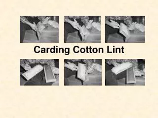
Raw material Web Sliver Carding Doffing Carding machine and drafting
Control system Drive act(t) set(t) Carding machine and drafting • Drafting – sliver mass irregularity reduction High-dynamic variable-speed drive.
Draft device • Performance improvement ? • Production speed time for drafting • Short-distance irregularity !!! • Solution: • Draft device dynamics improvement • Possible modifications • Simulation is necessary!
Draft device model • Draft process + electric drive.
Electric drive simulation • Math model of el. machine (permanent magnet synchronous motor) • Control structure of machine. • Model implementation in (Simulink Toolbox)
Model verification • Parameters of model acc. to real drive. • Comparison of time-domain and/orfrequency-domain responses.
Model utilisation • Testing methods of drive dynamics improvement: • Optimisation of regulator parameters (when analytical solution is difficult or impossible) • Modifications of control structure drive frequency bandwidthfBW • To test quality improvement of draft process.
Results • Drive dynamics improvement
Results • Sliver quality improvement
Conclusion • Complex simulation of draft process • Controllers parameter optimisation • Testing of innovative control methods • Real carding machine experiments • Time demanding (machine preparation) • Expensive (Raw textile material, energy, machine operator).
„Praxisorientierter Einsatz von Simulation“ Mathematical simulation of electrodynamic drive MSc. Josef Černohorský, Ph.D. Technical University of Liberec Faculty of Mechatronics and Interdisciplinary Engineering Studies Research Centre „TEXTIL II“
Requirements on the drive • Complex motion • Speed 2m/s • Precision 0.1 mm • Frequency 5 Hz • Mass up to 6 kg • Lenght of the machine up to 20 m
Implementation • ADSP 21992 • ADC – absolute position and current measurement • IRC – high resolution position measurement • CANbus – communication with high level control system • PWM – HEXFET power module control • FLAG and IOs • PC program for visualization and power board
Model and system differences • Current limitation • Current ripple • Estimation of current direction • Circuit solution • Noise on ADC • Position measurement • Speed controller • DSP control • Task planning, interrupts
Improvement of model • Current and voltage limitation • New block to model • Peak and continuous current limitation Improvement of design • Current measurement • Position IRC measurement • Respect EMC guidelines
Results of modelling • Mathematical model – better performance • Respect limitation of semiconductors • Implement assumed noise • Respect performance of your DSP • Acquire the time of task • Implement the delays to model • Make mixed model of whole system • Sampling frequencies, DSP task • Simulation difficulties, cost efficiency