Download
1 / 3
30 likes | 160 Views
LN2 Storage vessel. Nitrogen or helium gas. Nitrogen or helium gas. G1. G2. to TT10. 3. Magnet cryostat. 1. 4. buffer storage vessel. 2. VALVE BOX. Schematic diagram of the cryogenic system. System Operation. nToF11 SCHEMATIC DIAGRAM OF THE CRYOGENIC SYSTEM

E N D
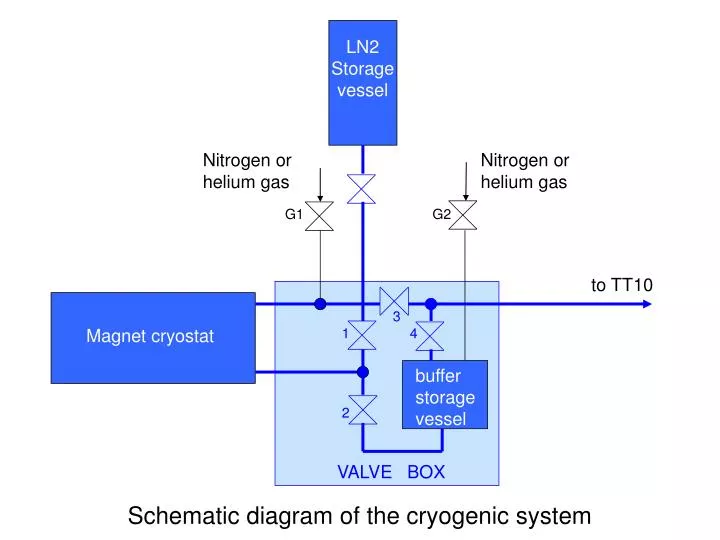
LN2 Storage vessel Nitrogen or helium gas Nitrogen or helium gas G1 G2 to TT10 3 Magnet cryostat 1 4 buffer storage vessel 2 VALVE BOX Schematic diagram of the cryogenic system
nToF11 SCHEMATIC DIAGRAM OF THE CRYOGENIC SYSTEM All valves and junctions are in the valve box All valves are remotely operable in TT2 Valve 1 is a proportional valve Safety pressure relief valves are not show Demountable joints LN2 lines Cold nitrogen gas lines Warm nitrogen gas line LN2 Storage vessel GROUND LEVEL heat exchanger TUNNEL TT2A to TT10 Magnet cryostat, 100 l G1 G2 nitrogen or helium gas 2 5 3 4 1 buffer storage vessel, 150 l TUNNEL TT2 VALVE BOX