Download
1 / 20
220 likes | 280 Views
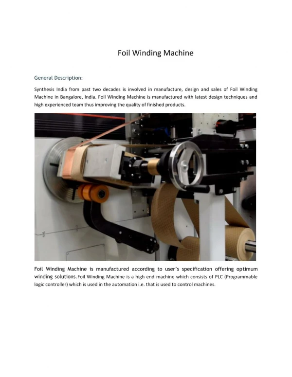
Chapter 4. Winding Editor. Workshop 3. WS03: Winding Editor. Workshop #3: Winding editor A simple arrangement of 3 phase coils in air is to be constructed using the winding editor. The objectives will be to calculate the field and self and mutual inductance.

E N D
Chapter 4 Winding Editor Workshop 3
WS03: Winding Editor • Workshop #3: Winding editor • A simple arrangement of 3 phase coils in air is to be constructed using the winding editor. The objectives will be to calculate the field and self and mutual inductance. 3 phase winding in air, 100 turns each iC = 1240° A iB = 1120° A iA = 10° A March 4, 2005 Inventory #002210 4-2
WS03: Winding Editor • Upon entering the workbench environment, choose new geometry. 1 March 4, 2005 Inventory #002210 4-3
WS03: Winding Editor • Change the desired unit length to millimeters. 1 2 March 4, 2005 Inventory #002210 4-4
WS03: Winding Editor • Bring up the Winding Tool. Set the number of slots to 6. • Define the “phase A” circuit as follows: • Comprised of 1 coil • 100 turns • Current flows into slot 1, out of slot 2 • End geometry is an arc • End clearance: 5 mm • Radius in/out: 50 mm • Cross section dimensions: 5 X 5 mm • Declare the XYPlane to be the center plane (steps 4-6 at right) • Click generate 5 7 4: Click in this box to activate the Apply/cancel buttons 1 6: Click Apply 2 3 March 4, 2005 Inventory #002210 4-5
WS03: Winding Editor • Use “Show Cross Section Solids” to display the full geometry of the coil. 1 March 4, 2005 Inventory #002210 4-6
WS03: Winding Editor • Create phases B and C in the table as shown in steps 2 – 4. Click on generate. The 6 equally spaced slot locations are shown at right. When the slot angle is zero, slot 1 lies on the XY plane of the base plane. 5 Slot 3 Slot 2 Slot 4 Slot 1 Slot 6 Slot 5 2 3 March 4, 2005 Inventory #002210 4-7 4
WS03: Winding Editor • Note the effect of modifying the slot angle. Temporarily change it to 30° and click generate. Restore to zero and click generate again. 30° March 4, 2005 Inventory #002210 4-8
WS03: Winding Editor • Note the effect of modifying the skew angle. Temporarily change it to 10° and click generate. Restore to zero and click generate again. March 4, 2005 Inventory #002210 4-9
WS03: Winding Editor • Note the effect of modifying the cross section length. Temporarily change it to 20 mm and click generate. Restore to 5 mm and click generate again. March 4, 2005 Inventory #002210 4-10
WS03: Winding Editor • Create a cylindrical enclosure aligned with the active (XYPlane) z axis extending 50 mm beyond the coil geometry. 3 1 2 March 4, 2005 Inventory #002210 4-11
WS03: Winding Editor • Save the geometry. 1 2 2 3 March 4, 2005 Inventory #002210 4-12
WS03: Winding Editor • Click on the Project tab and create a new simulation. 1 2 March 4, 2005 Inventory #002210 4-13
WS03: Winding Editor • Click on Environment in the tree with the right mouse button (RMB) and insert a magnetic flux parallel boundary condition. 1 (RMB) 2 March 4, 2005 Inventory #002210 4-14
WS03: Winding Editor • Hold down the CTRL button as you select (LMB) individual surfaces of the enclosure. Use the middle mouse button to rotate the geometry so that previously hidden surfaces face you, then add them to the selected set. • Once all 3 surfaces are selected, click Apply. March 4, 2005 Inventory #002210 4-15
WS03: Winding Editor • Define a 1 A current at a phase angle of 0° in conductor A. Similarly, define the following conductor currents: • Conductor B: iB = 1 120° A • Conductor C: iC = 1 240° A 1 2 March 4, 2005 Inventory #002210 4-16
WS03: Winding Editor • Inset a request for Total Flux Density calculations. 1 (RMB) 2 March 4, 2005 Inventory #002210 4-17
WS03: Winding Editor • Inset a request for inductance calculations and click Solve. We will not bother looking at the mesh. 3 1 (RMB) 2 March 4, 2005 Inventory #002210 4-18
WS03: Winding Editor • View the resulting flux density. You will at first find yourself looking at an opaque contour plot that hides the field quantities from view. Select buttons 2 – 5 to obtain the vector plot shown at right. 3 2 4 5 1 March 4, 2005 Inventory #002210 4-19
WS03: Winding Editor • Bring up the inductance matrix. The diagonal terms are coil self inductances. Off-diagonal terms are mutual inductances. 1 March 4, 2005 Inventory #002210 4-20