Download
1 / 52
520 likes | 552 Views
Chapter 20 Network Layer: Internet Protocol. By Prof. Ashutosh S. Werulkar , Department of Electronics and Telecommunication Engg. St. Vincent Pallotti College of Engg. and Technology, Gavsi Manapur, Vardha Road, Nagpur 0712-2701934(R) 9970621934(M) Email: ashutoshwerulkar@yahoo.com/gmail.com.

E N D
Chapter 20 Network Layer: Internet Protocol ByProf. Ashutosh S. Werulkar, Department of Electronics and Telecommunication Engg.St. Vincent Pallotti College of Engg. and Technology, Gavsi Manapur, Vardha Road, Nagpur0712-2701934(R)9970621934(M)Email: ashutoshwerulkar@yahoo.com/gmail.com
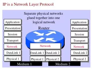
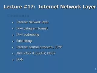
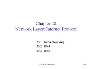
20-1 INTERNETWORKING In this section, we discuss internetworking, connecting networks together to make an internetwork or an internet. Topics discussed in this section: Need for Network LayerInternet as a Datagram NetworkInternet as a Connectionless Network
Figure 20.3 Network layer at the source, router, and destination
Figure 20.3 Network layer at the source, router, and destination (continued)
Note Switching at the network layer in the Internet uses the datagram approach to packet switching.
Note Communication at the network layer in the Internet is connectionless.
20-2 IPv4 The Internet Protocol version 4 (IPv4) is the delivery mechanism used by the TCP/IP protocols. Topics discussed in this section: DatagramFragmentationChecksum Options
Note The precedence subfield was part of version 4, but never used.
Note The total length field defines the total length of the datagram including the header.
Figure 20.7 Encapsulation of a small datagram in an Ethernet frame
Example 20.1 An IPv4 packet has arrived with the first 8 bits as shown: 01000010 The receiver discards the packet. Why? Solution There is an error in this packet. The 4 leftmost bits (0100) show the version, which is correct. The next 4 bits (0010) show an invalid header length (2 × 4 = 8). The minimum number of bytes in the header must be 20. The packet has been corrupted in transmission.
Example 20.2 In an IPv4 packet, the value of HLEN is 1000 in binary. How many bytes of options are being carried by this packet? Solution The HLEN value is 8, which means the total number of bytes in the header is 8 × 4, or 32 bytes. The first 20 bytes are the base header, the next 12 bytes are the options.
Example 20.3 In an IPv4 packet, the value of HLEN is 5, and the value of the total length field is 0x0028. How many bytes of data are being carried by this packet? Solution The HLEN value is 5, which means the total number of bytes in the header is 5 × 4, or 20 bytes (no options). The total length is 40 bytes, which means the packet is carrying 20 bytes of data (40 − 20).
Example 20.4 An IPv4 packet has arrived with the first few hexadecimal digits as shown. 0x45000028000100000102. . . How many hops can this packet travel before being dropped? The data belong to what upper-layer protocol? Solution To find the time-to-live field, we skip 8 bytes. The time-to-live field is the ninth byte, which is 01. This means the packet can travel only one hop. The protocol field is the next byte (02), which means that the upper-layer protocol is IGMP.
Example 20.5 A packet has arrived with an M bit value of 0. Is this the first fragment, the last fragment, or a middle fragment? Do we know if the packet was fragmented? Solution If the M bit is 0, it means that there are no more fragments; the fragment is the last one. However, we cannot say if the original packet was fragmented or not. A non-fragmented packet is considered the last fragment.
Example 20.6 A packet has arrived with an M bit value of 1. Is this the first fragment, the last fragment, or a middle fragment? Do we know if the packet was fragmented? Solution If the M bit is 1, it means that there is at least one more fragment. This fragment can be the first one or a middle one, but not the last one. We don’t know if it is the first one or a middle one; we need more information (the value of the fragmentation offset).
Example 20.7 A packet has arrived with an M bit value of 1 and a fragmentation offset value of 0. Is this the first fragment, the last fragment, or a middle fragment? Solution Because the M bit is 1, it is either the first fragment or a middle one. Because the offset value is 0, it is the first fragment.
Example 20.8 A packet has arrived in which the offset value is 100. What is the number of the first byte? Do we know the number of the last byte? Solution To find the number of the first byte, we multiply the offset value by 8. This means that the first byte number is 800. We cannot determine the number of the last byte unless we know the length.
Example 20.9 A packet has arrived in which the offset value is 100, the value of HLEN is 5, and the value of the total length field is 100. What are the numbers of the first byte and the last byte? Solution The first byte number is 100 × 8 = 800. The total length is 100 bytes, and the header length is 20 bytes (5 × 4), which means that there are 80 bytes in this datagram. If the first byte number is 800, the last byte number must be 879.
Example 20.10 Figure 20.13 shows an example of a checksum calculation for an IPv4 header without options. The header is divided into 16-bit sections. All the sections are added and the sum is complemented. The result is inserted in the checksum field.
20-3 IPv6 The network layer protocol in the TCP/IP protocol suite is currently IPv4. Although IPv4 is well designed, data communication has evolved since the inception of IPv4 in the 1970s. IPv4 has some deficiencies that make it unsuitable for the fast-growing Internet. Topics discussed in this section: AdvantagesPacket FormatExtension Headers
Table 20.10 Comparison between IPv4 options and IPv6 extension headers
20-4 TRANSITION FROM IPv4 TO IPv6 Because of the huge number of systems on the Internet, the transition from IPv4 to IPv6 cannot happen suddenly. It takes a considerable amount of time before every system in the Internet can move from IPv4 to IPv6. The transition must be smooth to prevent any problems between IPv4 and IPv6 systems. Topics discussed in this section: Dual StackTunnelingHeader Translation