Download

1 / 33
390 likes | 574 Views
Smart Home. GROUP 4 Daniel Arnett · Joseph Vanciel · Brian Krueger Advisor: Dr. Samuel Richie Sponsor: Workforce Central Florida Mentor: Sean Donovan. Motivation. Energy costs continue to rise

E N D
Smart Home GROUP 4 Daniel Arnett · Joseph Vanciel · Brian Krueger Advisor: Dr. Samuel Richie Sponsor: Workforce Central Florida Mentor: Sean Donovan
Motivation • Energy costs continue to rise • Energy independence is an important national issue, with energy conservation as a key component • With the advances in mobile technologies, people want increasingly more access and control over all aspects of their lives
Energy Consumption • In 2001, families with gross annual incomes below $50,000 spent an average of 12% of their average after-tax income on residential and transportation energy. • By 2005, energy costs rose to 16% of their average after-tax income. • In 2012, these households are projected to spend 21% of their average after-tax income on energy. (DOE/EIA Short-Term Energy Outlook released in January 2012) • The categories of home energy usage that this project aims to decrease are: • Home Electronics 7.2% • Lighting 8.8%
Goals Create a prototype for a “Smart House” that will: • Reduce energy consumption • Increase energy efficiency • Allow for home automation • Allow for remote access via a user friendly GUI delivered through an internet browser
Energy Savings • The first component of the project reduces energy consumption by shutting off unused lights by automatically sensing when someone leaves a room. • The problem with a setup that uses continuous sensor inputs alone is that once the sensors do not sense any activity, the lights will shut off in that room. • This is a problem if someone is in a room, but not moving, and the lights go out since no activity was sensed after a period of time.
Energy Savings • This project gets around this problem by placing motion sensors in each room and at each doorway. • If someone walks through a doorway, the sensors in each room will look for motion, thereby detecting if someone has left the room, or entered the room. • This will prevent the lights from turning off unless someone has left the room. This setup will conveniently allow someone to go from one room to another without having to turn lights off and on as they leave and enter rooms. • That convenience will be combined with the energy savings of eliminating instances where someone forgets to turn off lights in unoccupied rooms.
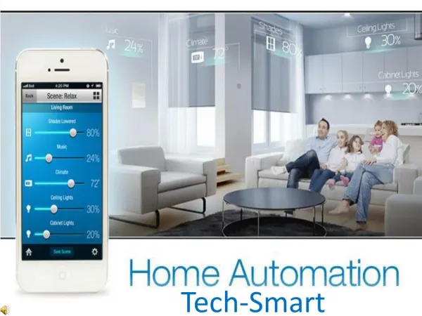
Remote Access • The second main component of the project is a website that is hosted on the main microcontroller that will allow a user to remotely access their devices connected to the network from any web browser. • There is a graphical user interface on the website which allows the user to view the status of and turn on and off lights and electronics in various rooms.
Requirements and Specifications • Scan adjoining rooms using PIR sensors for 30 seconds after doorway sensor is tripped and time out if no activity • Web interface reports back status of all lightsand electronics on the network • Update GUI automatically within 2 seconds of any device changing status • Toggle devices within 2 seconds of user request via the website • Website is broadcast over wireless network • Processors will remain in sleep mode when not performing calculations
Main Processor Functions • void UART_Config() • Initializes several variables (setting pin outs, initializing UART interrupts, configuring baud rate, stop bit, parity bit, word length) • void UART_Send(char dataOut) • Sends character to FIFO buffer to send out (8 bits) • char UART_Receive() • Returns character from FIFO buffer (8 bits) • void UART_Store(char address, int status) • Stores latest On/Off status of device at any given address at the status array • int UART_Retrieve(char address) • Retrieves default status at device at any given device from the status array
Main Processor Software • Protocol: UART • 8 data bits:
Motion MSP430 Functions • void initializeclock(void) • Initializes all the clocks used • void initializepins(void) • Initializes all inputs, outputs, and functionality of the pins • void initializecounter(void) • Initializes the internal counter for resending over UART • void initializeUART(void) • Initializes the settings for the UART protocol • void initializequeue(void) • Initializes the software queue used for UART messages
Functions cont. • void UARTsend(int) • Loads the queue with values to be sent • int verify(int) • Verifies if the door or room sensor actually tripped or if it was just noise • int occupied(void) • Logic the system goes through when a door sensor is tripped • void control(void) • Changes the outputs to the relay based on memory • void loadqueue(void) • Loads the queue with full status update when pinged from brain
Graphical User Interface • Once the user pulls up the IP address of the Server in their browser, the GUI will appear in the user’s web browser. • The GUI will • display the status of the lights and electronics in each room • allow the user to turn a light on or off by clicking the appropriate button • allow the user to turn an outlet on or off by clicking the appropriate button
Speaker: Brian Krueger Graphical User Interface (GUI)
Website Communication • The website was programmed in a way such that as the status of different electronics and lights change, the webpage is dynamically updated. • The website uses JavaScript running in the web browser to send HTTP requests for special URLs, depending on the button clicked and corresponding to the device that status is being sent to or requested for. • These special URLs are intercepted in the file system support layer (lmi_fs.c) on the Stellaris and used to communicate to both send a message to the corresponding MSP430 to change status as well as to store the latest status in the RAM of the Stellaris. • Responses generated by the Stellaris are returned to the browser and inserted into the webpage dynamically using more JavaScript code.
Remote Access-Routing • The PCB that contains the Stellaris LM3S8962 connects to the home’s internet connection through the Linksys WRT54G router via an Ethernet cable. • Since we are assuming that different people would have different routers, the choice of which router to use was fairly arbitrary, as the prototype would need to be compatible with a wide range of routers. • The Linksys WRT54G was chosen since it is a popular router which is reasonably priced • The main requirement for the router to be compatible would be that a user would be able to properly configure the router’s port forwarding
Remote Access Configure HTTP forwarding: • Application: HTTP • External port: 80 • Internal port: 80 • Protocol: TCP • IP Address: 192.168.200 Configure HTTPS forwarding: • Application: HTTPS • External port: 443 • Internal port: 443 • Protocol: TCP • IP Address: 192.168.1.200 Configure RWW forwarding: • Application: RWW • External port: 4125 • Internal port: 4125 • Protocol: TCP • IP Address: 192.168.1.200
Testing Environment for motion sensors
Final Testing – Electrical • All individual components were tested to make sure they were working including: • All MSP 430 PCB boards • Motion sensors PCB boards • Relay PCB boards • Lights • Outlets
Final Testing – Functional • Each individual outlet and light were sent a toggle signal from the website, the corresponding device was correctly toggled within 2 seconds, and the correct status was updated on the website within 2 seconds • One at a time, each doorway sensor was tripped, and we made sure that both adjoining lights came on: • each room sensor was tripped and we made sure that room’s lights came on, and the other adjoining room whose sensor was not tripped turned off within 30 seconds • when any light was turned on or off, the website updated the status within 2 seconds
Final Testing – Functional • Due to the way we wrote the code, both the MSP 430 and Stellaris are interrupt driven, and each system will only awake upon interrupt, and will return to sleep after processing each interrupt • Upon system startup, the IP address of the project’s website is displayed on the OLED of the Stellaris, which is connected to the router. The router then makes the Stellaris available over any internet connection as well as over the broadcasted wireless network
Budget and Financing Funding was provided by Work Force Central Florida
Special thanks to: Workforce Central Florida Dr. Samuel Richie Sean Donovan for all their help and support!