Download

1 / 20
210 likes | 255 Views
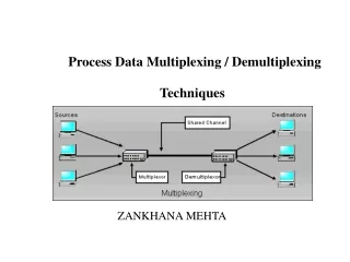
Multiplexing and Demultiplexing. Multiplexing. There are several data inputs and one of them is routed to the output Like selecting a television channel In addition to data inputs, there must be select inputs How many select pins are needed? Depends on number of inputs

E N D
Multiplexing • There are several data inputs and one of them is routed to the output • Like selecting a television channel • In addition to data inputs, there must be select inputs • How many select pins are needed? • Depends on number of inputs • Multiplexer aka MUX
Algebra for 2-to-1 MUX • Take expressions for 1’s found in truth table • SAB + SAB + SAB + SAB • This can be factored as follows • SA(B+B) + S(A+A)B • (B+B) = 1 • Not B or B, doesn’t care about B • SA + SB
Gates for 2-to-1 MUX S0A S0B
Addresses • Each data input is assigned to a specific state of the select input • E.g. low-low, low-high, high-low, high-high • The state can be interpreted as binary numbers • 00, 01, 10, 11 • Two select Four addresses • And these numbers are thought of as the “addresses” of the input
Demultiplexing • one input is routed to one of several outputs • Like mail may be sent to any number of recipients • In addition to data input, there must be select inputs • To select from 2N data outputs requires N select inputs • Demultiplexer aka DeMUX
Decoder • A variation on the previous circuit is to have no input data • the selected output will be high, the others low • This can be used to activate a control pin on the selected part of circuit
Decoder plus registers = RAM • Memory Address Register (MAR) holds an address associated with memory • Memory Data Register (MDR) holds data for writing to memory • Memory is a sequence of registers and a decoder • Decoder output is connected to control pins (load in this example) of the RAM
Decoder plus registers = RAM Load pins MDR Decoder MAR
The logic of ROM fuse Address lines Decoder “Burned” fuse
Logic of ROM (Cont.) • Fuses connect output of decoder to output of ROM • Normal voltage and current does not burn (“blow”) the fuse • So when the selected decoder output is high, all ROM output lines to which it is connected are also high
Logic of ROM (Cont.) • Higher voltage and current will break the connections • They are applied selectively to break certain connections • The ROM output is not affected by the decoder output if the connection is broken • (Implementation may be different, but this is the basic logic)