Download
1 / 14
140 likes | 227 Views
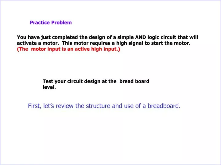
Practice Problem. You have just completed the design of a simple AND logic circuit that will activate a motor. This motor requires a high signal to start the motor. (The motor input is an active high input.). Test your circuit design at the bread board level.

E N D
Practice Problem You have just completed the design of a simple AND logic circuit that will activate a motor. This motor requires a high signal to start the motor. (The motor input is an active high input.) Test your circuit design at the bread board level. First, let’s review the structure and use of a breadboard.
The Breadboard What You See What You Don’t See:
Horizontal strip of copper wire. Horizontal strip of copper wire. The Breadboard What You Don’t See: Two rows of short isolated vertical strips (70 single strips per row) of copper wire Horizontal strip of copper wire. Horizontal strip of copper wire.
25 nodes per horizontal row section The Breadboard Power and ground rails Power Supply + - 5 nodes per vertical column + 5 volts 0 volts 5 volt horizontal panel Ground ( 0 V )
Power and ground rails Power Supply + - 25 nodes per horizontal row section 5 nodes per veridical column + 5 volts 0 volts The Breadboard A node is a point where two components of a circuit can be connected.
The Breadboard Vertical Column (5 Node) : Each Vertical Column on the face of the board has a strip of metal underneath the board connecting the 5 holes. This allows 5 different circuit elements to be connected and have the same voltage value. +5 volt node connection Ground, 0 V, node connection Each column of the breadboard is electrically isolated from its neighbor
The Breadboard The Trench (A nonconductive groove which isolates 2 groups of vertical columns) The “chip” Chips are to be installed across the Trench In this case, the chip is called a 7408 and it houses four AND logic devices.
The Breadboard The chip with the identification number 7408 is always a chip that contains AND devices. How many AND devices are in a 7408 chip?
Input # 2 for AND device C Input # 1 for AND device C The Breadboard Output for AND device B Pin 14 Input # 1 for AND device A Input # 1 for AND device D Input # 2 for device D A Output for device D Pin 1 C B D Pin 8 Input # 2 for AND device A Pin 7 Output for AND device A Input # 1 for AND device B Output for AND device B Input # 2 for AND device B There are 4 AND devices in the 7408 package. The 7408 is know as a quad 2 input AND package.
The Breadboard In order to perform its function each chip must have a connection to the Power (5V) and to the Ground (0V) What are the possible pins that could be used for the power and ground connection? Input # 1 AND device A Input # 2 AND device A Input # 1 AND device C Output AND device A Input # 1 AND device C Input # 1 AND device A Output AND device C Input # 1 AND device D Input # 2 AND device A Input # 1 AND device D Output AND device A Output AND device D There are two pins left. One is for the power connection, the other is for the ground connection. Which one goes to which pin?
In order to perform its function each chip must have a connection to the Power (5V) and to the Ground (0V) What are the possible pins that could be used for the power and ground connection? Input # 1 AND device A Input # 2 AND device A Input # 1 AND device C Output AND device A Input # 1 AND device C Input # 1 AND device A Output AND device C Input # 1 AND device D Input # 2 AND device A Input # 1 AND device D Output AND device A Output AND device D The Breadboard The terminal where the 5 volt wire is connected. + 14 - 7 The terminal where the zero volt wire is connected, (the ground connection).
14 7 The Breadboard Where are the power and ground connections for this 7408? How many pins does a 7408 have? 14 Which one is the pin where the 0 volts, the ground connection, is made? Which pin is pin number 8? Which pin is pin number 14? ? Power (+5 Volts) Which pin is pin number 7? Note: If you hold the chip so you can read the label “DM 7408N”, Then the 5 volt pin is the last pin on the left side of the top row of pins. Which pin is pin number 1? ? Ground ( 0 Volts)
Battery powered Volt meter + The Breadboard Practice Problem You have just completed the design of a simple AND logic circuit that will activate a motor. This motor requires a high signal to start the motor. (The motor input is an active high input.) Now let’s return to the initial problem statement Test your circuit design at the bread board level. When the two inputs (input A and input B) are at logic 1 the output will be at logic 1 and the meter will display 5 volts. Draw your test circuit on a piece of paper before you continue with this presentation. Power (+5 Volts) 1 A ( input ) 1 1 4.96 0 B ( input) 0 Volts
Battery powered Volt meter + The Breadboard Practice Problem You have just completed the design of a simple AND logic circuit that will activate a motor. This motor requires a high signal to start the motor. (The motor input is an active high input.) Now let’s return to the initial problem statement Test your circuit design at the bread board level. When the two inputs (input A and input B) are at logic 1 the output will be at logic 1 and the meter will display 5 volts. Draw your test circuit on a piece of paper before you continue with this presentation. Power (+5 Volts) 1 A ( input ) 1 1 4.96 0 B ( input) 0 Volts