Download
1 / 39
390 likes | 399 Views
Pumping well challenges for Producers with the advent of horizontal drilling along with pad drilling in some fields. Visit: https://westernfalcon.com<br>

E N D
Canadian Artificial Lift Conference 2018 Thermoplastic Liners A Cost Effective Option to Reduce Downhole Failures in Pumping Wells Earl Sperling February 28, 2018
. Conestoga Supply Conestoga Pipe & Supply Warbird Tubular Processors
Presentation Outline • Pumping well challenges for Producers with the advent of horizontal drilling along with pad drilling in some fields. – How can producers increase production while reducing lifting costs ? • Methods to control downhole corrosion and rod on tubing wear in pumping wells. • Review of Thermoplastic Lined (TPL) Tubing. • Show how TPL tubing can reduce the coefficient of friction (COF) and rod load in horizontal pumping wells. • Case economic studies showing how TPL tubing can reduce downhole failure frequency and result in lower lifting costs. • Conclusions
How can producers increase production while reducing lifting costs in Pumping Wells? • In many cases lowering the bottomhole pump into the bend can increase production. • Consequences in lowering the pump into the bend with conventional downhole designs. – Added capital to rod and tubing string designs – Increased well work-overs due to increased weight and friction: • Rod breaks , rod overload and/or buckling • Rod on tubing wear failures • Corrosion failures – Increased rod load means higher energy costs
Beam Pumping Wells
Progressive Cavity Pump (PCP) Wells
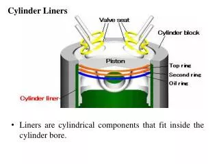
Corrosion of Tubing Wall + Rod Wear Schematic Corrosive Wear
Controlling Downhole Corrosion in Pumping Wells • Metallurgy • Chemical Treatment • Internal Plastic Coatings (IPC) • Thermoset Composite (GRE) Pipe, Sucker Rods, & Tubing Liners • Thermoplastic Liners (TPL)
Controlling Downhole Rod on Tubing Wear in Pumping Wells • Molded Rod Guides • Rod Rotators • Tubing Rotators • Tubing Anchors • Spray Metal Rod Couplings • Roller Rod Guides • Continuous Rod Strings • Coatings & Metal Surface Treatments • Thermoplastic Liners (TPL)
Polycore Tubular Lining Products 71 71° °C (Oil) 82 C (Oil) 82° °C (Water ) C (Water )
Surface Roughness Western Falcon Polycore™ lined tubing is 30 Times smoother than NEW bare tubing (0.00006 vs. 0.0018 inches) New BARE tubing typically will become approximately 30 to 35 Times rougher (than new) during service from corrosion Thanks to Osborne Reynolds • Absolute Roughness 0.002 0.0015 0.001 • 0.0005 Rz DIN 0 Western Falcon Polycore Lined Tubing NEW Bare Tubing
Pressure Drop in Lined Tubing @ 2,500 bpd PSI PER 100 FT. • Lined tubing ID is approx. 0.30-inch (7.6 mm) less than bare pipe • Even at higher velocities and same flow rate, the smoothness of the liner overcomes the ID restriction of the liner. 3.5 3 2.5 Bare 2 Poly Lined 1.5 1 0.5 0 2 7/8 3 1/2 API Tubing Size 10 psi/100 ft. = 2.262 kPa/m
ConocoPhillips Rod Friction Test Summary¹ – Drag Ratio • Plotting the drag ratios vs. temperature yields the relationship on the right • Testing funded and supported by ConocoPhillips ¹Coupling Friction in HDPE Lined Tubing, 2009 Permian Basin AL Forum, Mike Berry, Rob Davis, John Patterson
Coefficient of Friction of Sucker Rods in Downhole Tubing Rod load made up of rod weight and friction. The coefficient of friction (COF) times the side load is equal to the frictional force on the sucker rod. Lufkin’s S-ROD² uses a bare rod COF default value of 0.2 for bare rods. If molded rod guides are used then the COF increases and the S- ROD² default value becomes 0.3. A reasonable conclusion is to assume that the COF of TPL tubing (Polycore™)to bare sucker rods with couplings in oil pumping wells is at least 35 to 45% less¹ than the bare tubing and sucker rod COF. Target a COF of 0.12 for TPL tubing. Dynamometer diagnostic work with and without TPL tubing can further tighten the COF numbers. ²Rod Pumping Deviated Wells, Lufkin Automation, Jun Xu,Ken Nolen,Dennis Shipp, Andy Cordova,Sam Gibbs • • • • • •
Beam Pump Rod Prediction Duvernay Horizontal Well (Pad Drill) Modelling information provided by End User Design Depth meters All molded rod guides *Molded and roller rod guides No rod guides 2,900 0.2 TPL Tubing, no rod guides COF % of allowable rod load 147 Max. side Load lbs/rod 461 3,075 0.42 3,075 0.02 - 0.42 87 356 97 85 324 311 2,900 0.12 Pump stroke rate and rod type and size the same for all cases. Side load seen throughout the string, a pad drill. *Initial design was molded and roller rod guides, operability was an issue. Recommendation; Ultratube™ lined tubing with spray metal rod couplings. • • • •
Molded Rod Guides vs. TPL Tubing • Molded Rod Guides – Increased friction vs. bare rods & tubing – Increase Load on Rods – Rods fail from Fatigue quicker – Compromises Pumping Depth – No Corrosion Protection to Tubing ID – Fixed on Rods and Wear out on Tubing • TPL Tubing – Decreased friction vs. bare rods & tubing – Decrease Load on Rods – Rods Have Longer Fatigue Life – Can Pump Deeper – Protects Tubing ID from both Corrosion & Wear – Create Elastic Buffer by Moving relative to both Tubing ID & Rods
Limitations of Thermoplastic Liners (TPL) NOT indestructible – handling & running procedures • Protectors on threads until make-up and after breakout of connection • Must select proper polymer for the well environment • TEMPERATURE • Horizontal and deviated wells: predicted side load • Permeable to acid gases - PVT info. • Any pumping well downhole failure information Adds slight amount of weight to tubing string • • • Creates ID restriction
Virden Area Producer; Beam Pumping Wells Vertical & horizontal beam pumping wells, typical depth 950- 1050 meters • TVD, BHT 25-35 C, 2 7/8 inch tubing o Pump set at 70 to 90 degrees off vertical in horizontal wells Rod on tubing wear, corrosion and rod breaks, worst wells 10 months run • life In June 2013, began installing Polycore™ lined tubing in problem wells • (3 ½ & 2 7/8 inch lined tubing) o have not been back on wells since lining (only pump change-outs) o Minimum polished rod loads lower resulting in lower potential of rod buckling o Payout less than 10 months (less than 1 work-over) To date lined 110 wells, plan to line about 50 wells/yr. •
SE SK Bakken Producer, Beam Pumping Wells • Horizontal wells, Well depth ~ 1,500 meters TVD, build rate15°/30m, 69°C B/H temperature. • Lowered the B/H pump (65 to 70° off vertical) into the build section to increase oil production. • Running 3 ½ inch Ultratube™ lined tubing with spray metal rod couplings in the build section to prevent rod on tubing wear. • Rod breaks from buckling was an issue without TPL tubing. • >50 beam pumping wells lined with Ultratube™ in the past 3 yr. • No issues to date except one well where severe corrosion in the middle of the sucker rod created sharp edges that cut the liner. o The recommendation in this case would be to use 10 foot pony rods with spray metal rod couplings in the build section to minimize contact with the rod body.
Ultratube™ North Dakota Bakken Beam Pumping Wells • Depths TVD 2,440 to 3,050 M, bottomhole temperatures 100 to 138˚C. • Corrosion and rod on tubing wear a big problem in the build section, tried setting the pump in the horizontal; however, kept breaking pump barrels. • Predicted side loads typically vary between 300 to 400 lb./rod; however, some wells as high as 800 lb./rod. • Tried a number of methods to extend tubing life. • The most effective way to extend tubing life has been to install Ultratube™ lined tubing with connected rods and spray metal couplings. • Liner shavings were only seen in wells with standard (mild steel similar to continuous rods) rod couplings that corroded creating sharp edges that cut the liner. • Have run Ultratube™ lined tubing in over 200 North Dakota Bakken beam pumping oil wells in the past three years.
Provost Field PCP Wells Lined with Polycore™ Deviated and horizontal wells, up to 250 M3/d of fluids with 95% water cut and an average of 8% CO2 in solution gas. Repeat tubing failures after 7 months in this corrosive environment using molded rod guides and corrosion inhibitor. Over 50 wells lined with Polycore™ in the early 2,000’s 2000 Report: • Work-over cost decreased: • Additional revenue of: • Total average benefit of: Well Lined with Polycore™ in 2002 • May 2014 tubing leak in one (1) of the wells. • Hole in the boronized joint just above the PCP due to wear and corrosion. • Polycore™ liner looked good after 12 years service. • Installed Extremetube™ pup joint above the PCP. • • • • $ 1,262/month/well $ 1,172/month/well $ 2,434/month/well
Provost, AB Lined Used Tubing After 12 Years of Service in PCP Well
Alderson Field SE AB Area PCP Wells • Producer purchased 200 wells in late 2014, 20 wells had been lined with 3 ½ inch Polycore™, 15 PCP producers and 5 water injectors • Typical depth 1,050 M TVD, BHP 4,800 kPa, BHT 30 C • Early 1st Qtr. 2015, Producer compared non-lined to Polycore™ lined wells in the past 3 years • Work-over frequency, rod breaks, rod on tubing wear failures, corrosion • Pump torque, energy savings • Producer concluded that Polycore™ lined tubing provided significant value • Now in wells needing work-overs, bare tubing is replaced with Polycore™ lined Producer used 3 ½ inch tubing.
Grand Forks Field, SE AB, Horizontal PCP Oil Well First production Sept, 2014. Pump depth 908 meters MD, 870 meters TVD, 2 7/8 inch tubing, 1 inch continuous rod. Production 240 M3/d, 96% water cut, oil 9.6 M3/d, gas 300 M3/D (3% CO2, 2% H2S), B/H temperature 30°C. PCP NOV 120-1200, 242 RPM, torque 1045 ft.-lbs. December, 2015 work-over due to connection back-off at 350 meter from surface, the majority of the tubing string showed severe ID pitting corrosion. CFER rod program predicts maximum side load of 13 lb/ft. in the build section. Modelled by End User. • • • • • •
Grand Forks Field, SE AB, PCP Well, Dir. Survey Pump depth 908 meters MD, 870 meter TVD
Grand Forks Field Horizontal PCP Well Lined Tubing Energy Savings March, 2016, ran 334 meters of 3 ½ inch Modified Polycore™ lined blue band used tubing in the bottom section. Recommended lining the entire string. PCP NOV 120-1200, 242 RPM before and after installing lined tubing, Production 240 M3/D – Pump torque before lined tubing 1,045 ft-lbs (47 hp (35 kw)) – Pump torque after lined tubing 300 ft-lbs (13 hp (10 kw)) Energy Savings assuming cost of $0.07/kwh is $15,330/yr. Cost of lined tubing $10,600. If the entire string was lined the cost would be $29,000. Lift costs energy savings alone is $0.75/BOE. • • • • • •
Worsley Field, NW AB, PCP Heavy Oil Wells Pump depth 1,050-1,192 meters MD, 1,037–1,072 meters TVD, 3 ½ inch tubing, continuous rod. Production, water 140-700 bbl./d (85-97% water cut), oil 24-65 bbl./d (15.6 API), gas 0.1-325 mscfd (3-6% CO2), B/H temperature 40°C. PCP set at 70-75° off vertical Severe corrosion of tubing strings and the continuous rod, worst wells 6 months life (85% of tubing and continuous rod replaced) CFER rod program predicts maximum side load of 12-17 lb/ft. (300- 425 lbs/rod if connected rod) in the build section of 2 wells. Modelled by End User. Installed 3 ½ inch Polycore™ lined yellow band tubing in a number of wells in the 1st and 2nd quarter of 2016. • • • • • •
Worsley Field, NW AB, PCP Heavy Oil Wells Lined Tubing Inspection in Wells No. 1 & 2 • Installed 3 ½ inch Polycore™ lined yellow band tubing in March 2016 • In June 2017 after 15 months service the lined tubing was pulled to install a larger PCP to handle more fluid. • The lined tubing was found in excellent condition and the continuous rod show only superficial corrosion. • Both the lined tubing and continuous rod were run back in the hole.
Economic Model Worsley Field Heavy Oil Wells • • • • • • • • • • • • • • • • Tubing Cost per Meter (CDN) Liner Cost per Meter (CDN) Oil Price per Barrel (USD, exchange rate 1.3) Gas Price per MCF (USD, exchange rate 1.3) Start Date Evaluation Period (Months) Tubing String Depth (Meters) Oil Production Rate (BBL/d) Gas Production Rate (mcf/d) Lifting Cost per Barrel ($CDN/BOE) Average Annual Production Decline (Percent) Previous Workover Frequency (Months) Lost Production Days per Workover Percent of Tubing String Replaced per Workover New Workover Frequency for Pumps (Months) Base Workover Cost (CDN) 20 20 30.00 1.5 15-May-2016 60 1,100 31 trace 16.50 10 6 5 85 24 60,000.00
Economic Model Worsley Field Heavy Oil Wells Economics does not include any energy consumption savings •
Conclusions Thermoplastic lined tubing has proven to be the longest runtime solution in many wells by reducing rod load and downhole failure frequency. Detailed diagnostic analysis of pumping wells can greatly assist in determining the most cost effective solution to increase production and reducing lifting costs. – Predictive rod load programs. – Dynamometer diagnostic work comparing actual rod loads to predictive rod loads. – Rod break frequency. – Rod on tubing wear and corrosion failure frequency. – Production losses due to downtime and/or non-optimal pumping well design – Energy savings with reduced rod loads. • •