Download
1 / 31
310 likes | 314 Views
This document explores the use of UML in the systems engineering process for developing system requirements. It discusses the benefits of using UML in capturing and analyzing user needs, integrating abstract and physical views, and following industry standards. With UML, the communication challenge between customers and engineers can be addressed effectively.

E N D
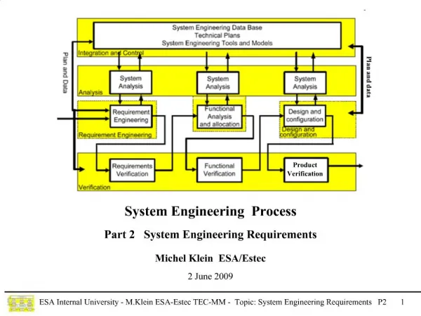
On Using UML in the Systems Engineering Process for System Requirements Development Pete Ross, Shawn Simmons, Michael Crow The Boeing Company Integrated Defense Systems
1.0 Introduction1.1 Need for Improved Methods of Implementing SE Process 1.2 Where OOA, UML, and Related Tools Help2.0 Comprehensive Requirements Analysis and Management Through Models & Databases2.1 UML Use for Enhanced Definition & Communication of Requirements 2.2 Executable Modeling for Requirements & Design Analyses3.0 Summary
Many Platforms, Highly Integrated Integrated Air Platforms Integrated Air And Ground Systems Integrated Ground Platforms Common Operating Picture And Information Available At All Echelons Highly Integrated Systems Engineering Processes are Needed to Meet The Challenges Of Large Scale Integration Of System of Systems
The System Engineering Environment Has Changed Future Concepts Delta Launch Vehicle F-22 Operational Needs Are Continuously Changing Systems Technologies are Constantly Evolving Therefore Requirements Evolve Continuously during A Development Program • Future • System-of-Systems Solutions • For Network Centric Operations • Flexibility/Agility • “Time to Market” Focus • Commercial Practices and Products • MDA/ Effects Based Development • Quality at Each Step of Process • Present • Integrated Systems • Rapid Prototyping • COTS • Affordability Focus FA-18 C/D Systems Engineering Processes Must Support Flexibility Throughout Development Process • Past • Performance Driven • Military Specs • Federated Systems • Focus on Delivered Quality
The Communication Challenge • Capture and Integrate Operator Intended Usage to Properly Turn User Needs into System Requirements • Need to keep customer in the loop well into the development process • For efficiency and clarity, need to be able to effectively communicate with the intended users in a language that both they and the contractor team understand Customer Communicates in the language of a technology domain ? Communicates in the language of a use domain Engineer • Capture and Integrate Analyses of Many Domain Experts to Properly Turn User Needs into System Requirements • Increased emphasis on well organized and maintainable capture and analysis of user and inter-/ intra- system processes in a variety of situations • For efficiency and clarity, need integrated processes, modeling languages, and tools • Address Legacy Structured Analysis and Design Technique Shortfalls • Tends to drive federated solutions • Low support for showing linkage of functional decomposition back to intended use
ICD ICD . AV ICD: Internal ICDs Internal ICDs The Systems Integration Challenge For SoS Architectures Increased Focus of Integration at the Highest Level and Therefore Complexity From Both the Operators and Developers Point of View Force Structure Level 1(Context) Requirements Detail Allocates to System Land Sea Space JTF/AOC Air Theater Command & Control Processes/Interactions DOD AF Intent is to Bridge these Levels System Developers View Users Operational View Command & Control Segment Radar Segment Air Vehicle Segment Weapon System Level 2 (Concept) Allocates to Segment Functional & Physical Architectures Integrated Processor eg. Console, Comm gear eg. Cockpit, airframe, engine Major Subsystem Level 3 (Logical) Allocates to SubSys Integration Has Been Focused At This Level Over Last Decade Traditional SE Processes Have Not Been Proven To Be Efficient Subsystem Level 4 Allocates to CSCI/HWCI HWCI & CSCI Level 5 Allocates to HWC and CSC
Build SDS 9/10/02 Definition ofSystem Requirements Function & Performance Allocations Integrated Processes, Common Semantics Visual Models, and Common Format Portable Data Customer L1 Operational Function & Performance System L2 System Function & Performance Systems Engineering Segment L3 Segment Function & Performance Subsystem Allocate requirements to: Product Engineering L4 Subsystem Function & Performance CSCI & HWCI Test and Evaluation L5 CSC Function & Performance Test CSC Linear Time Representation Of Requirements Development Process t
represents changes in attributes or operation activations represents operations in use Class Activity State Attributes Operations Elements used to model a real world object and its behavior OOA/ UML Benefits Captures Life Cycle Uses of System By Formal Analysis of Multiple Use Cases Integrates Abstract Physical & Behavioral Views Using Object Oriented Analysis Commercial and defense industry software development standard modeling language UML is a standardized language Which has Continued software and systems engineering support
OOA: Abstract modeling and analysis of real world objects behavioral interactions and architectural relationships Apply Content Decomposition Hierarchically to Aid in System Requirements Analysis OO is Used to Bound the Levels and Support Information Technology Based Descriptions of the System UML: UML captures the results of OOA UML is an industry standard for conceptual/ visual modeling Specified and maintained by non-profit Object Management Group (OMG) UML is a language not a methodology Concepts, Semantics, Notation, Rules Example Diagram Types Sequence Diagrams Use Case Diagrams Activity & State Diagrams Class Diagrams What Are Object Oriented Analysis and Unified Modeling Language? • 8 Diagram/View Types: Activity, Class, Collaboration, Component, Deployment, Sequence, State, Use Case
OOA/ UML Supports Decomposition of Use, Behavior, Objects, Data, and Interface Types Captures Scenario Dependent Behavior Taxi to Point Receive Coordinated Mission Start Clearance Form-Up for Coordinated Taxi <<extend>> <<include>> <<include>> <<include>> Taxi Coordinated to Taxi Hold-Point <<include>> Taxi Coordinated to Point <<extend>> <<include>> Perform Final Pre-Flight Tests <<include>> Taxi Coordinated to Take Off Taxi/ Take Off for Specific Hold-Point Scenarios 1 & 2 Take Off Air Vehicle Use Decomposition Flight Package 1 1 1..n 1..n Mission Commander Piloted Strike System 1 1 1 0..n 0..n 0..n Content Decomposition Pilot Air Vehicle JDAM Small Diameter Bomb
OOA/ UML Used to Capture Interface Behavior One Level at a Time : Pilot : Air Vehicle : Operation Commander Completed Prepare System Completed Prepare System Pre-Mission Scenario Phase Pre-Mission Scenario Phase Approve Mission Start Request Mission Start Communicate Clearance Clearance Request Receive Communicate Clearance Clearance Stimulus-Response Activity Modeling Between System and Externals, Repeated at Next Level for Segment-Segment, Segment-Externals, and Similarly Through Remaining Decomposition Levels Provides Deterministic Means of How Far to Decompose Functionality at Each Level Ready to Request Taxi Clearance
UML Supporting Technologies OMG is working to provide a vision, framework, and definition at all levels of software and systems development on a non-proprietary basis MDAtm (Model Driven Architecture) OMG Vision Emerging Technologies XMI xUML Profiles & Patterns Action Semantics Design Tags Code Templates Modeling Standard UMLtm (Unified Modeling Language) Modeling Methodology Object Modeling Methodology Model Driven Development Process Process
Integration With Performance Requirements Analysis Tools & Processes An adequate means to capture and manage performance requirements Need visual models to capture timing and motion requirements Need visual models for performance parameter decomposition/ allocation Adequate functional architecture views for use as a framework for trade-offs of physical architectures and performance allocation analyses Adequate semantics for combined behavioral and performance simulations xUML provides some capability in this area Integration With Physical Modeling Tools & Processes Adequate physical views for capturing and managing physical interfaces, physical allocation analyses, and non-functional requirements Integration With Classical System Engineering Processes Integrated cost, performance, schedule, risk models for use in trade-off analyses What is needed beyond OOA/ UML?
2.0Comprehensive Requirements Analysis and Management Through Models & Databases 2.1 UML Use for Enhanced Definition & Communication of Requirements 2.2 Executable Modeling for Requirements and Design Analyses
2.1 UML Used for Enhanced Definition & Communication of Requirements
The Coordination Challenge Product Engineering Customer Stakeholders Systems Engineering Test and Evaluation Integrated Processes, Common Semantics Visual Models, and Common Format Portable Data Matrices/ Databases Graphs Simulations Block Diagrams Drawings Function X Time Map Best Models & Data Constructs to an Integrated SE Process Use UML Model as Focal Point to Tie Together Engineering Products
Multi-Discipline Participation in Use Case DrivenArchitecture Development & Design System Effectiveness, Reliability System Con Ops, Safety, Security Interoperability Measures of Effectiveness Architecturally Significant Mission Scenarios Nominal Use Threads Contingency Threads Performance Requirements Database Abstract Use Case “Operate System” Architecturally Significant Mission Scenarios Identify Functional Interaction of System with External Participants And Use of IERs UML Model Context Diagrams, Process Flows, Use Descriptions, Item Exchanges, Candidate Technology &Solution Objects Classes
Views Need to Convey All Aspects of Each Level Of The Architecture To All Stakeholders Cubes Represent Engineering Data & Architecture Products Specialized Views Like Security Are Created For Each Level From Data Across the Rows Integration & Test Team Product Team Time People Network Function Data Motivation L1 Requirements Analysis User/ Customer Functional Analysis L2 Synthesis L1 L2 L3 L4 L5 The Products Developed are Organized Based on the Zachman Framework The goal of Using a Framework is to Ensure an Architecturally Complete Description
Engineering Products Provide Forum and Canvas for Product Definition and Refinement Measures of Effectiveness Capabilities External Systems Architecturally Significant Mission Scenarios Use Cases (for all life cycle phases) Product Relationships Provide Linkage To Intended Use Scenarios Threads Modes Views States Activities Database Performance Functional Architecture Physical Architecture
Superstate A State II State I State III State Diagram State IV Class 4 Object A Object B Object C Attributes Activity 3 Activity 2 Activity 1 Activity 4 Activity 5 Attribute x Attribute y Operations Node A Component 1 Operation p () Operation q () Operation r () Component 2 Node B Component 3 Component 4 Construction of The Functional ArchitectureAnd Allocated To The Physical Architecture State Diagram Class Diagram Class Association (roles) Relationships Deployment Diagram
Integrated Process & Environment for Deriving Behavioral Requirements Performance Analysis Use Driven and Methodical Requirements Derivation Safety, Health, Quality, Security, Survivability, Concepts Life Cycle Phases External Systems Capabilities UML Use Cases Activities Threads Use Scenario Script Driven Verification Using Logic and Timing Simulations Modes States Functional Architecture State Model Matrix Performance Model IDEF Interactive Simulation Performance Linking performance with functional architecture to validate Architecture meets Measures of Effectiveness is key
Integrate Commercially Available Tools UML Tool Best Of Breed Toolsets Should Be Combined to Achieve Maximum Integration Across System Engineering Tasks System Engineering Toolsets Should Be Chosen To Be Synergistic With Software Engineering Environment Requirements Management Database Risk Tool Trade Studies Performance Analysis Modeling Change Management
2.2 Executable Modeling for Requirements and Design Analyses
System Analysis Requirements Analysis Analysis & Control Loop Requirements Loop Functional Analysis / Allocation Design Loop Verification Loop Synthesis Iteration Loop Where Executable Modeling Fits In In the Development Process • To Meet System Analyses Needs: • Capacity (bandwidth) • Security • Fault Tolerance • Interoperability • Interference • Operator Awareness • Control Logic, Timing, Accuracy • Safety (Maintain Physical Separation) • Timelines and accuracies required to Carry out Mission Objectives • Supports SE Information Needs: • Critical Function Partitioning • Data for Systems Engineering Trade Studies and “what if” analysis. • Data to Verify requirements and architecture completeness. • Data to Verify interface definition.
Build SDS 9/10/02 Relationship of Executable Modeling toVerification and Validation Function & Performance Allocations Executable Modeling is performed Using the analysis model of the “To be built” System Op Eval System Exercise L1 Function & Performance System Executable Modeling L2 System Function & Performance Segment Test Validation Segment Verification L3 Segment Function & Performance Subsystem Test Subsystem Allocate requirements to: CSCI & HWCI Test L4 Subsystem Function & Performance CSCI & HWCI V&V Testing Is performed On the As-built, As coded system With Hardware In the Loop CSC Test L5 CSCI Function & Performance CSC The Role of Executable Modeling is to Verify the Requirements for Consistency And Validate that the requirements meet the requirements from the level above
Transitioning From Functional Modeling to Executable Modeling AV Class Superstate A State II State I State III State Diagram State IV Object A Object A Object A Object A Object B Object B Object B Object B Object C Object C Object C Object C Activity 1 Activity 5 Activity 3 Activity 4 Activity 5 Activity 5 Activity 1 Activity 2 Activity 3 Activity 4 Activity 4 Activity 1 Activity 1 Activity 2 Activity 3 Activity 4 Activity 5 Activity 3 Activity 2 Activity 2 Operation 1 A State Model Is Developed for Each Class Operation 2 Operation 3 …… Operation n Bring together Physical, Functional, Data to Evaluate Logical Consistency & Performance
System Analysis & Tool Suitability • Context Level Architecture Analysis • Concept Modeled As A “Black Box” • Model of Domain Elements as Sources • And Sinks Context: Force Structure Concept: Weapon System Logical: Segment • Concept Level Architecture Analysis • Segment Elements Modeled • As “Black Boxes” • Domain Elements Modeled as Sources • And Sinks Communications Analysis Capacity (bandwidth) Latency (delays) Security Fault Tolerance Interoperability Interference Operator Awareness • Logical Level Architecture Analysis • Physical Elements Modeled • As “Black Boxes” • Concept Elements Modeled as Sources • And Sinks Tools Should Be Chosen to Best Fit The Needs of the Purpose of the Analysis
Best Solution for Behavioral Requirements Development Strongly and clearly driven by concepts of use and documented knowledge of required interfaces with other systems. Use case based approach fosters multi-discipline participation Provides Appropriate (Use Oriented) Focal Point to Organize and View Other Model Artifacts Provides Clear Traceability of Derived Behavioral Requirements Saves $$$ for changes and supports spiral development Provides Strong Foundation for Engineering & Design Processes Automation Large industry investment and support from Software Engineering Using UML In TheSystem Engineering Process Design Of Highly Integrated Systems Require Integrated SE Processes Adoption of a UML based Object Oriented Architecture Centric SE Process That Uses Modeling and Simulation As Its Core, Meets That Need A Disciplined Architecture Centric Systems Engineering Approach Will be Required to Provide Interoperable C4ISR Systems to Meet The Challenges of Information Dominance