Download

1 / 86
880 likes | 1.18k Views
Plant & Electrical Distribution Systems. Module ENGE 303 H.Gallagher@gcal.ac.uk hugo@logis-tech.co.uk Tel No: 0141 331 …. Room M… Week 1. Recommended Text. J.O Bird, Electrical Circuit Theory and Technology , Revised edition (Chapters 7, 8, 9)

E N D
Plant & Electrical Distribution Systems • Module ENGE 303 • H.Gallagher@gcal.ac.uk • hugo@logis-tech.co.uk • Tel No: 0141 331 …. • Room M… • Week 1
Recommended Text • J.O Bird, Electrical Circuit Theory and Technology, Revised edition (Chapters 7, 8, 9) • T.Floyd, Electronic Fundamentals, Circuits, Devices and Applications, 6th Edition (Chapter 7)
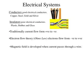
The Magnetic Field • A permanent magnet has a magnetic field surrounding it. • Consists of lines of force that radiate from the north pole to the south pole and back to the north pole through the magnetic material.
The Magnetic Field • Consists of lines of force, (or flux lines), that radiate from the north pole (N) to the south pole (S) and back to the N. pole through the magnetic material. • The many lines surround the magnet in 3 dimensions. • Lines shrink to the smallest possible size and blend together;- although they do not touch. • Forms a continuous magnetic field surrounding the magnet.
Fig. 3 Effect of (a) nonmagnetic and (b) magnetic materials on a magnetic field.
Magnetic Flux, Φ • The group of force lines going from the N. pole to the S. pole of a magnet is called the magnetic flux, symbolized by Φ (phi). • No. of lines of force in a magnetic field determines the value of the flux. • The more lines of force, the greater the flux and the stronger the magnetic field. • Unit of magnetic flux is the weber (Wb) • One weber = 108 lines.
Magnetic Flux Density, (B) • Is the amount of flux per unit area perpendicular to the magnetic field. • Its symbol is B, and its unit is the tesla (T). • One tesla = one weber/square meter (Wb/m2). • The following expresses the flux density: B =Φ A • Φ is the flux, A is the c.s.a in square meters (m2) of the magnetic field.
The Gauss • The tesla (T) is the SI unit for flux density, another unit called the gauss, from the CGS (centimeter-gram-second) system, is sometimes used (104gauss = 1T). • The instrument used to measure flux density is the gaussmeter.
Example 1 • Find the flux density in a magnetic field in which the flux in 0.1m2 is 800μWb. • Solution B = Φ/A = 800μWb/0.1m2 = 8000μT
Example 2 • A magnetic pole face has a rectangular section having dimensions 200 mm by 100 mm. If the total flux emerging from the pole is 150 μ Wb. Calculate the flux density. Solution: • Φ = 150 μ Wb = 150 x 10-6 Wb • c.s.a = 200 x 100 = 20000 mm2 = 20000 x 10-6 m2 Flux Density, B = Φ/A = 150 x 10-6/20000 x 10-6 = 0.0075 T or 7.5mT
How Materials Become Magnetised • Ferromagnetic materials become magnetised when placed in the magnetic field of a magnet. • We have all seen a permanent magnet pick up paper clips, nails, or iron filings. • Objects becomes magnetised under the influence of the permanent magnetic field and becomes attracted to the magnet. • When removed from the magnetic field, object tends to lose its magnetism. • Ferromagnetic materials have minute magnetic domains created within their atomic structure by the orbital motion and spin of electrons. • These domains can be viewed as very small bar magnets with N. and S. poles.
Figure 4 Magnetic domains in (a) an unmagnetized and in (b) a magnetised material.
Application Example Figure 5 Operation of a magnetic switch
Quiz 1 • When the North poles of two magnets are placed close together, do they repel or attract each other? Ans: The North Poles repel • What is magnetic flux? Ans: Magnetic flux is the group of lines of force that make up a magnetic field. • What is the flux density when Φ = 4.5μWb and A = 5 x 10⁻³ m2? Ans: B = Φ/A = 900μT
Electromagnetism • Is the production of a magnetic field by current in a conductor. • Many types of useful devices such as tape recorders, electric motors, speakers, solenoids, and relays are based on electromagnetism.
Fig. 9 Magnetic lines of force around a current-carrying conductor
Electromagnetic Properties • Permeability (μ) • The Relative Permeability (μr) • Reluctance, S (RM)
Permeability (μ) • Ease with which a magnetic field can be established in a given material is measured by the permeability of that material. • Higher the permeability, a magnetic field can be established easier • Symbol μ; its value varies depending on material. • μo, permeability of a vacuum is 4π X 10-7 Wb/At.m (weber/ampere-turn.meter) and is used as a reference. • Ferromagnetic materials typically have; • permeabilities hundreds of times larger than that of a vacuum • include iron, steel, and their alloys.
The Relative Permeability • (μr) of a material is the ratio of its absolute permeability (μ) to the permeability of a vacuum (μo). • Since μr is a ratio, it has no units. μr =μ μo
Reluctance (S) • Opposition to the establishment of a magnetic field in a material is called reluctance (S). • Value of reluctance is directly proportional to the length (ℒ) of the magnetic path, and inversely proportional to the permeability (μ) and to the c.s.a. (A) of the material; • S = ℒ/μA (At/Wb)
Example 2 • What is the reluctance of a material that has a length of 0.05 m, a cross-sectional area of 0.012 m2, and a permeability of 3500 μWb/At.m? • Solution: S = ℒ/ μA = 0.05/ (3500 x 10-6 Wb/At.m) (0.012m2) = 1190 At/Wb
Magnetomotive Force (mmf) • Current in a conductor produces a magnetic field. • Force that produces the magnetic field is called the magnetomotive force (mmf). • Unit of mmf, (At), is established on the basis of the current in a single loop (turn) of wire. • Formula for mmf is: Fm = NI Fm is the magnetomotive force, N is the no. of turns of wire, I is the current in amperes.
Ohm's law for magnetic circuits • The amount of flux depends on the magnitude of the mmf and on the reluctance of the material, as expressed by: Φ =Fm R
Example 3 • How much flux is established in the magnetic path of Fig. 12 if the reluctance of the material is 0.28 X 10⁵At/WB? Figure 12
Solution to Example 3 • Φ = Fm/R = NI/R = (5 t) (3 A) 0.28 X 10⁵ At/Wb = 5.36 X 10⁻⁴ Wb = 536μWb
Example 4 • There are two amperes of current through a wire with 5 turns. • (a) What is the mmf? • (b) What is the reluctance of the circuit if the flux is 250 μWb? Solution (a) N = 5 and I = 2A Fm = NI = (5t)(2A) = 10 At (b) R = Fm/Φ = 10At/250μWb = 0.04 X 10⁶ At/Wb = 4.0 X 10⁴ At/Wb
The Electromagnet • A basic electromagnet is simply a coil of wire wound around a core material that can be easily magnetised. • The shape of the electromagnet can be designed for various applications.
Figure 13 Reversing the current in the coil causes the electromagnetic field to reverse.
Application Examples Figure 14 Read/write function on a magnetic surface.
The Magneto – Optical Disk • Uses an electromagnet and laser beams to read and write (record) data on a magnetic surface. • Formatted in tracks and sectors similar to magnetic floppy disks and hard disks. • Laser beam precisely directed to an extremely small spot • Capable of storing much more data than standard magnetic hard disks.
Electromagnetic Devices • Magnetic disk/tape read/write head • Magneto-optical disk • Transformer • Solenoid • Relay • Speaker
The Solenoid • Is a type of electromagnetic device that has a movable iron core called a plunger. • Movement of this iron core depends on both an electromagnetic field and a mechanical spring force.
The Relay • Differs from solenoids in that the electromagnetic action is used to open or close electrical contacts rather than to provide mechanical movement.
Reed Relay • like the armature relay, uses an electromagnetic coil. • Contacts are thin reeds of magnetic material and are usually located inside the coil.
Example 5 • With the aid of a sketch, explain the operation of the electromagnetic relay. • Also provide an example of an application of this type of device? Solution • Reference should be made to the reed relay and /or the armature relay. • electromagnetic action is used to open or close electrical contacts • unenergised/energised • Structure • Symbol
The Speaker • Permanent-magnet speakers are commonly used and their operation is based on the principle of electromagnetism. • Constructed with a permanent magnet and an electromagnet. • Cone of the speaker consists of a paper-like diaphragm to which is attached a hollow cylinder with a coil around it, forming an electromagnet.