Download
1 / 27
270 likes | 330 Views
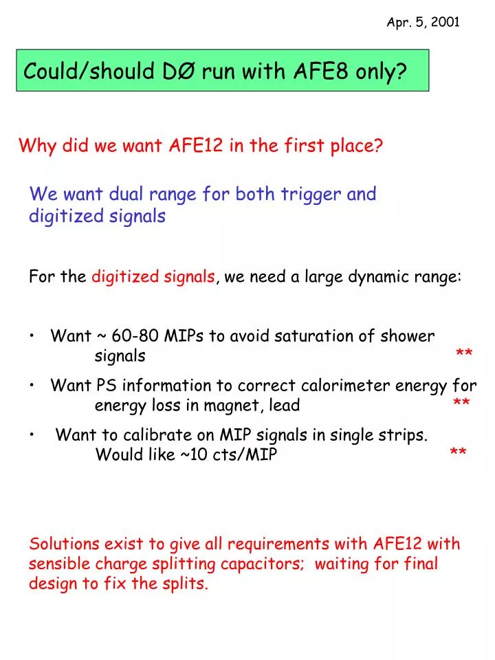
Apr. 5, 2001. Could/should DØ run with AFE8 only?. Why did we want AFE12 in the first place?. We want dual range for both trigger and digitized signals For the digitized signals , we need a large dynamic range:

E N D
Apr. 5, 2001 Could/should DØ run with AFE8 only? Why did we want AFE12 in the first place? • We want dual range for both trigger and digitized signals • For the digitized signals, we need a large dynamic range: • Want ~ 60-80 MIPs to avoid saturation of shower signals ** • Want PS information to correct calorimeter energy for energy loss in magnet, lead ** • Want to calibrate on MIP signals in single strips. Would like ~10 cts/MIP ** • Solutions exist to give all requirements with AFE12 with sensible charge splitting capacitors; waiting for final design to fix the splits.
PS use for Cal EM calibration Need CPS energy to regain CCEM resolution, particularly at high h. At h = 0.95, want CPS energy deposit calibration to < 10% Need for FPS calibration not as severe, but still needed
MIP Calibration 10 counts/MIP Select strips with neighbors < 10% For 80 hits per strip, rms < 3%. No special selection other than requiring that neighbor strip be < 0.1 MeV Want 10 counts/MIP (in high gain channel) Get sample in 1 hr with event rate of 10 Hz (moderate ET jet triggers)
For trigger, want two thresholds available • Want threshold in range 2 – 5 MIPs to allow low energy electron, di-electrons, tri-lepton triggers (J/Y, U, b e X, chargino/neutralino trileptons … ) • For W/Z, top, Higgs triggers, want higher threshold to help control rates at high luminosity. (Will perhaps not use preshower elements in W/Z triggers until it is absolutely necessary for rate control, since we want the most efficient and least biassed triggers possible.)
CPS axial and stereo signals are mixed with CFT stereo on AFE12 boards. 64 CPS signals per VLPC/cassette module split on MCM board to the dual MCM daughterboards from modules 3,4,5,6. ** n.b. Although VLPC’s for a given detector are chosen to have ~equal gain, this does not mean that they have the same bias voltage!
1 2 3 4 5 6 7 8 8 MCM Cassette (2 Analog Front End Bd) CFT Right hand bd Left hand bd 64 64 1 8 North (front) 64 64 7 2 64 64 6 3 64 64 4 5 64 64 4 5 South (back) 64 64 6 3 64 64 2 7 Board top Board top 64 64 8 1 Backplane Backplane MCM daughter boards (SIFT+SVX) 64 channels used Warm fiber/VLPC modules. 64(E) and 64(W) waveguides /module VLPC chips -- 8 pixels/chip
64 64 64 1 2 3 64 64 64 64 4 5 6 7 8 C1 C2 Cd 12 MCM Cassette (2 AFE Bd) CPS/CFT stereo Right hand bd Left hand bd 64 64 CFT stereo CFT stereo 1 12 North (front) 64 64 CFT stereo CFT stereo 11 2 CPS low 64 CPS low 3 10 4 9 high high CPS low CPS low 5 8 6 7 high high CPS low CPS low 7 6 5 8 South (back) high high CPS low CPS low 9 4 10 3 high high 64 64 CFT stereo CFT stereo 2 11 Board top Board top 64 64 CFT stereo CFT stereo 12 1 Backplane Backplane MCM daughter boards (SIFT+SVX) 64 channels used Warm fiber/ VLPC modules 64(E)& 64(W) waveguides /module VLPC
FPS is more complicated since there are 103 MIP layer strips (103 < 128 !) 144 SHWR layer strips (144 = 128 + 16 !) divert 16 SHWR strips to modules 2 & 7 together with MIP strips ** 16 strip crossovers in uand in v
Crossover strips now are at low eta (in shadow of solenoid; no lead preceding). It is thought that recabling FPS could make the high eta (small angle) strips be the crossovers.
FPS from detector to MCM - only shown for 12 MCM AFE right (v) DB j North DB j South C1 C2 Cd North AFE right -- v strips (12 MCM AFE left (u strips) is mirror image, through West ports ) 55 FPS MIP 55 103 55 1E 1 MIP sect j v strips North u 48 48 48 U strips FPS MIP 2E 2 16 192 72 SHWR sect j v strips North 72 FPS Sh lo 3 72 64 3E u 4 hi 96 24 64 72 FPS Sh lo 48 4E 5 24 48 hi 6 192 DFEF 48 24 64 72 FPS Sh lo 7 48 5E SHWR sect j v strips South 24 hi 8 96 72 u 64 9 FPS Sh lo 72 6E 192 72 hi 10 16 48 48 FPS MIP 48 MIP sect j v strips South 7E U strips 11 u 55 55 103 55 8E FPS MIP 12 Backplane clear waveguide cables - 16 channels/cable Flex cable LVDS DFE / daughter bds VLPC chips 8 pixel/chip FPS (v) detector strips Warm fiber VLPC modules -- 64E (+64W) waveguides /module
Up Cassettes for FPS-- from East end 1 16 1E 2 15 Spare 3 2E 14 FPS N 8 FPS S 8 12 MCM CFT Stereo 8 MCM 3E 4 13 East West East 4E East FPS N 7 FPS S 7 12 MCM 5 12 5E CFT Stereo 8 MCM 6 11 6E 7 FPS N 6 FPS S 6 12 MCM 10 8 9 7E CFT Stereo 8 MCM South FPS (from IP) Down 8E FPS N 5 FPS S 5 12 MCM CFT Stereo 9E 8 MCM FPS N 4 FPS S 4 12 MCM 10E CFT Stereo 8 MCM 11E FPS N 16 FPS S 16 12 MCM 36W FPS N 3 FPS S 6 12 MCM 12E CFT Stereo 8 MCM 37W CFT Stereo 8 MCM 13E FPS N 15 FPS S 15 12 MCM 38W FPS N 2 FPS S 2 12 MCM 14E CFT Stereo 8 MCM 39W CFT Stereo 8 MCM 15E FPS N 14 FPS S 14 12 MCM 40W FPS N 1 FPS S 1 12 MCM 16E CFT Stereo 8 MCM 41W FPS N 13 FPS S 13 12 MCM 42W Up CFT Stereo 8 MCM 43W 16 1 15 2 FPS N 12 FPS S 12 12 MCM 44W 14 3 CFT Stereo 8 MCM 45W 4 13 West East FPS N 11 FPS S 11 12 MCM 46W 12 5 CFT Stereo 8 MCM 47W 11 6 FPS N 10 FPS S 10 12 MCM 48W 7 10 West 9 8 CFT Stereo 8 MCM 49W FPS N 9 FPS S 9 12 MCM 50W North FPS (from IP) Down Spare 51W Cassettes for FPS-- from West end
Different VLPC classes for MIP and SHWR; modules 2 & 7 have both types. Special modification to cassettes to provide bias voltage appropriate for specific VLPC chips. MCM 1 MCM 2 MCM 3,4 MCM 5,6 Different bias voltages needed shower shower MIP
Why would we think of abandoning AFE12 now ? • *** Without CFT (axial and stereo) tracking, *** *** DØ is not an experiment. *** • Much (1/3) of CFT stereo readout is on AFE12 (mingled with CPS axial/stereo) • Guess at optimistic AFE12 schedule: 6 wks toM’bd prototype; 4 more wks to D’ bd proto; 4 wks test prototype; 2 wks bid/procure; 4 wks bare bd production; 4 + 4 wks bd assembly; 4 wks prod. bd test; ready to install Xmas (2001). later if use the AFE8 experience! (n.b. others have guessed AFE12 by September) • These considerations had led to plan for spare (throwaway) AFE8 bds; use for the remaining CFT stereo channels until AFE12’s ready. Requires extra 30 AFE8 bds; if only populate the CFTst, need 120+spares MCM’s to be removed and put on AFE12 later. Estimates vary on efficiency of removal of MCM’s (75% -- 25%) • quote (Sanmina) for 28 extra AFE8 bds = $37K. DØ finances not up to this (or even $10K). Do not exercise quote. • There are several people spending time now on AFE12 design/layout; this manpower could be useful for AFE8 debug/test/commission.
Why would we think of abandoning AFE12 now ? Consider permanent replacement of AFE boards for CFT stereo/CPS with AFE8’s. Stop all design work on AFE12 boards (FPS) for now. FPS in the end could be done with AFE12 or with modified AFE8’s (modification is change in bias voltage feed to accommodate the crossover channels in FPS cassettes as built and threshold references.) Pro’s: fastest way to full CFT and CPS reduce costs -- expect AFE8 to be roughly half of AFE12 cost (no ‘spare’ AFE8 now) Can redirect some manpower to AFE8 production Con’s: FPS is still late (either AFE12 or AFE8’ (end of year??) loss of functionality for CPS trigger/offline And: Still need some redesign for FPS even if done in AFE8’ Schedule for extra AFE8: 3 months to procure and test??
Options 1. Do nothing -- just complete AFE8 and get full CFT/PS when the AFE12 comes of age (2002??) 2. Buy the insurance of 28 extra AFE8 boards to tide us over AFE12, then scrap when we get AFE12 3. Buy 28 extra AFE8 boards now and leave on CFTstereo/CPS for Run IIa. Start on AFE12 or AFE8’ for FPS when we can. 4. Buy extra AFE boards for CPS/CFTst AND for FPS now (48 boards). Scrap plans for AFE12 Option 1 is ugly Options 2 and 3 may differ down the line, but have the same next step -- order the 28 AFE8 boards identical to those now being made. These schemes become different when we restart design of AFE12 of AFE8’, or when we decide whether to populate new AFE8 with 4 or 8 MCM’s Option 4 differs only in number of AFE8 extras to buy
Can we operate CPS (FPS) with AFE8 successfully? Will certainly lose the dual range trigger. This means either losing the capability for J/Y etc. triggers or not using CPS in W/Z triggers. My guess is that we would not want to put CPS into W/Z triggers until it is absolutely needed for rate control -- why add extra inefficiency, trigger corrections etc.? J/Y studies are mainly for early low luminosity running? But Susy trilepton searches will continue through the run. Preshowers used to regain good CAL energy resolution; this requires that we not saturate below ~60-80 MIPs. We must be able to calibrate preshower strips relatively. We had planned to use single MIPs for this. So we are fighting for dynamic range. Standard AFE8 parameters (VLPC gain, SIFT gain etc.) give saturation for preshowers. That’s why we had charge splits on Preshower inputs. Are there appropriate working conditions for CPS/FPS? (remember that CPS strips see roughly 3 times signal at ends of strips as at 90o )
Varying bias voltage can change QE, Gain, Noise, Charge = QE x Gain. Can ‘tune’ charge downwards by factor 3 or so before QE falls off; upward tune dependent on where the noise rate is too high, but probably not more than 30% increase from nominal. QE Gain Noise Charge
Settings with AFE12 CPS settings FPS settings 85% 13.6 33.8
Current plan for AFE12 prototype is to omit the ‘virtual SVX’ – reads out the SIFT discriminator bits for the preshowers to Level 3. (heat dissipation on close-spaced daughter boards, total power to AFE, space for CPLD chips) Loss is that we do not have a record of discriminator bits set at L3 for debugging the operation of the digital L1 trigger algorithm. The bits of course go directly to the DFEA, DFEF, DFES boards. The Glink outputs for disc. bits to L3 could be installed for CPS stereo and FPS, not CPS axial. We are investigating sending CPSax bits to CTOC boards for L3 during special operation. 640 bits per CTOC to L3; may be OK.
If we operate preshowers with AFE8 as is • There is only one gain/trigger threshold. We thus lose dynamic range. With the standard VLPC gains, unsplit signals saturate at only a few MIPs, so we cannot see SHWR signals – cannot correct the Calorimeter energy and thus lose EM resolution. • We may lose at least the 24 FPS crossover strips in both trigger and digitized data streams; their VLPCs not biassed appropriately. • Can’t set desired high thresholds • SVX saturates ; can’t see shower deposits
If we can reduce charge input to SIFTs, have a much better situation. If keep 25% - 35% of charge and standard SIFT/SVX transfer gains: X Can probably live with the dynamic range in this case … some truncation for very large ET electron/photons but not all PS layers will saturate (only one needed for CAL correction). 5 counts/MIP is marginal for MIP relative calibration. These calculations need independent confirmation !
To reduce the charge presented to SHWR layer SIFT: • Can reduce bias to lower QE and gain, but must avoid too small QE where probability of 0 pe becomes large. Perhaps reduce charge to ~50% • Can lower input capacitor value to SIFT (from 100 pF to 10pF) and get as low as 25% input charge transfer. Simple component change on board. • Charge split = CIN / (CIN + CCABLE ) = CIN / (CIN +30 pF) • Combination of the above two changes should give enough flexibility to solve Shwr layer range Charge Would prefer not to modify the AFE boards that take CFT stereo/CPS since we need these first. Modification to AFE8 for FPS needed anyway to allow crossover channel bias control.
Calibration is an issue. Correction of calorimeter energy for early shower contribution requires < 10% relative calibration of preshower strips (absolute calibration unneeded – fit the sampling fractions for best resolution). Monte Carlo study showed that MIP calibration was rather unstable when the digitization is as coarse as 3 counts/MIP, but it may still be possible ?? Could have special calibration run with high (0.4 - 0.5) SIFT to SVX transfer gain; gives ~10 ct/MIP. Requires that AFE operation is stable over long enough times to avoid frequent calibrations. Could think of relative calibration of CPS using f symmetry of shower deposits. Such relative calibration for FPS is difficult, as the strips are at different eta (different energy particles), and with variable material in front. Running preshowers with AFE8 would regain the virtual SVX readout, hence better ability to debug. (a minor bright spot !)
Effect of differential nonlinearity on AFE8 preshower operation. (not so different for AFE12 !) Operating conditions suggested above have 4-8 counts/MIP. DNL peaks at 8 counts would then be roughly at 1 -2 MIP intervals. The mean deposit in the preshower for 40 GeV electrons is about 45 MIPs (**) Thus might expect a jitter of +/- 0.5 - 1 MIP due to DNL would be a few % shift from true to observed energy. Our spec is to have calibration of preshower scale to 10%, so it seems that the DNL does not strongly affect ability to correct the Calorimeter energy at the W/Z. Calibration of the Preshower was expected to use single MIP traversals. DNL at level of +/- 0.5 MIP will clearly render this method unusable. Recourse would be to use azimuthal symmetry for high energy electrons from standard data stream. No study of this. For forward preshower this won’t work.
Summary: We can imagine operating preshowers with AFE8: Losses: cannot trigger on both high and low energy e/g . Someone’s physics suffers dynamic range suffers (would compromise MIP calibration ability at best; at worst, would saturate Shower layer strips for trigger and SVX digitization) Possible loss of the 24 cross-over channels because VLPC bias not appropriate Problems to be solved: How to reduce the charge seen at input to SIFT? modify VLPC bias voltage (changes to AFE8 cassettes for preshower signals). Believed possible for x2 reduction modify AFE8 board input cap. to give effective charge division? Seems possible to give x 3-4 reduction. . Time to to develop vendor and produce extra AFE8s for CFT stereo/CPS use ~ 3 months??Another 3-4 months for FPS AFE8 or AFE12 ?? Added manpower needed to develop new order