Download
1 / 23
230 likes | 253 Views
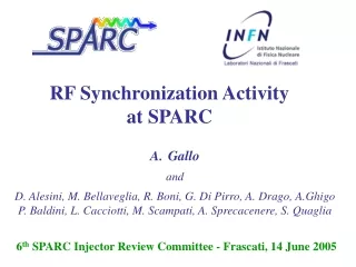
Timing and synchronization at SPARC. M. Bellaveglia On behalf of the SPARC/X timing, synchronization and LLRF group. Summary. SPARC general overview Synchronization and timing systems Overview Phase detection techniques Feedbacks and PLLs in the system Two beams synchronization

E N D
Timing and synchronization at SPARC M. Bellaveglia On behalf of the SPARC/X timing, synchronization and LLRF group
Summary • SPARC general overview • Synchronization and timing systems • Overview • Phase detection techniques • Feedbacks and PLLs in the system • Two beams synchronization • SPARC future plans • Electrons-photons interaction: SPARC towards LI2FE • LI2FE synchronization • Conclusion
SPARC general overview PLASMON-X SEEDING LASER PHOTOINJECTOR LASER THOMSON HHG DGL PHOTOINJECTOR UNDULATOR
SPARC synchronization system overview • One optical master oscillator • Feedbacks with BW <<1Hz, ≈5kHz and ≈1MHz to synchronize the subsystems • Shot-to-shot (10Hz) analysis for amplitude and phase calculation
SPARC timing system overview Line synchronization 50Hz PC laser amplification pump 1KHz RF reference 79.33MHz Trigger box 1KHz PC laser oscillator 79.33MHz Frequency divider 10Hz RF reference 2856MHz PC and seeding lasers Machine trigger distribution 10Hz Frequency divider 1KHz Diagnostics • Input • Output • Electrical • Optical • Transduction RF triggers
Phase detection – standard mixing technique Sampling Board DtRMS ≈ 55 fs • Tested Sampling Boards: • ADLINK 9812: 12-bit, 4-channels, 20 Ms/s • ADLINK 9820: 14-bit, 2-channels, 65Ms/s • NI PXI 5105: 12-bit, 8-channels, 60 Ms/s • Console application: • Real time base band analysis: phase noise and amplitude measurements • Possibility in choosing waveform analysis
Phase detection – Resonant method DtRMS ≈ 250 fs • 2142MHz cavity design to avoid RF interference with accelerating structures • Cavity exited by very short pulses: (i) e.m. field of the beam or (ii) output of a high voltage PD excited by the UV laser • Phase detection is possible using the decay time of some us inside the cavity • 250fsRMS time of arrival jitter observed in both the laser and bunch monitor
Phase detection – Deflector centroid jitter SPARC RF deflector Imageof a SPARC bunchverticallystreaked on a target Measurementof the beamcentroidvertical jitter t ≈ 150 fsRMS
PLLs - Klystron Fast Phase Lock Phase shifter To waveguides Error amp PLL on: Dt≈77fsRMS From reference • The phase noise introduced at the RF power generation level can be reduced by phase locking the klystron output to the RF reference with an analog loop: same concept as phase loops in CW machines; • Short time available to reach steady state (≈1ms): wideband loop transfer function (≈1 MHz) required. PLL off: Dt≈630fsRMS
Two beams synchronization – IR-UV on cathode IR beam • Experiment to try to modulate the electron beam during the photo emission • Delay line in the IR optical transfer line to synchronize the beams • Coarse synch (same bucket, <360ps): HV photodiode illuminated by the two beams and 5GHz oscilloscope to see the pulses overlap in time • Fine synch (“zero” delay): electron extracted by both the beams and accelerated until the RF deflector UV beam electrons RF GUN DEFLECTOR SCREEN
Two beams synchronization – FEL seeding Undulator SR LASER SEED SCREEN
Two beams synchronization – FEL seeding • Same approach than the IR+UV experiment • Both the beams are optical and more precisely: (i) the spontaneous radiation of the electron beam and (ii) the seeding laser pulse • Coarse synchronization (about 1ns): photodiode and oscilloscope (500MHz BW is enough) • Tuning the undulator section for spontaneous we were able to see both the signals on the oscilloscope and to overlap the electrical pulses • Also we observed the spectrum of the two beams tuning the spontaneous in the same wavelength range of the seed (400nm)
Two beams synchronization – FEL seeding • Fine synchronization: when the coarse synchronization was finished, we tuned the undulator sections to let the electron beam interact with the seed and we slightly moved (5mm) the optical delay line of the seeding laser • We immediately observed the seed amplification at the spectrometer screen @400nm
SPARC future plans - SPARC towards LI2FE SPARC nominal parameters PLASMON-X SEEDING LASER FLAME parameters PHOTOINJECTOR LASER THOMSON HHG DGL PHOTOINJECTOR UNDULATOR
SPARC future plans - LI2FE Experiments Plasma acceleration SPARC and Flame pulses injected in a gas jet, requires synchronization at the level of the period of the plasma wave. Experiments: PLASMONX Request: Δt<100fsRMS • Thomson scattering • Requires physical overlapping of SPARC and FLAME beams within the depth of focus of the laser focusing optics. • Experiments: PLASMONX, MAMBO • Request: Δt<1psRMS
SPARC future plans - LI2FE synchronization • Current layout • PC laser oscillator is the OMO • Electrical reference distribution • FLAME not yet considered FLAME AREA FLAME oscillator In 2856MHz Out 79.33MHz SPARC HALL PC laser Oscillator 79.33MHz RF reference 2856MHz RF reference 79.33MHz
SPARC future plans - LI2FE synchronization • 1st solution – electrical distribution • Easiest and quickest • Low cost • Coaxial cable distribution • Possible temperature stabilized cable bundle • Hundreds of femto-seconds performance FLAME AREA FLAME oscillator In 2856MHz Out 79.33MHz RF reference 2856MHz SPARC HALL PC laser Oscillator 79.33MHz RF reference 2856MHz
SPARC future plans - LI2FE synchronization FLAME AREA • 2nd solution – optical distribution • Fiber laser OMO (Optical Master Oscillator) • Major system modification needed • Higher cost • Fiber links to distribute the signal (active length stabilization) • Optical mixing (cross correlation) for laser clients • Sub-100fs performance FLAME oscillator 79.33MHz SPARC HALL OMO 79.33MHz PC laser Oscillator 79.33MHz RF reference 2856MHz
Conclusion • Synchronization system performance • System is inside project specifications • New diagnostic methods developed (BAM, LAM) • e-beam to RF jitter: ≈200 fsRMS • Seeding experiment successful • Future plans: electrons-photons interaction • Possible solutions and relative jitter: • Electrical reference distribution: 100÷200 fsRMS • Optical reference distribution: <100 fsRMS