Download
1 / 39
390 likes | 403 Views
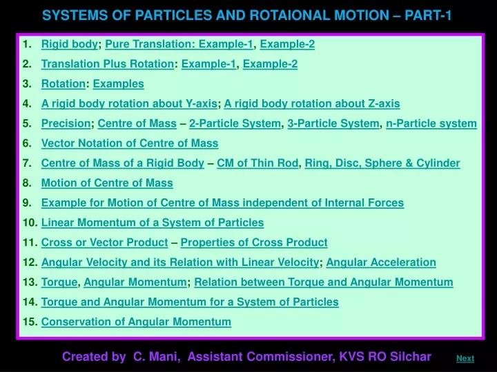
SYSTEMS OF PARTICLES AND ROTAIONAL MOTION – PART-1. Rigid body ; Pure Translation: Example-1 , Example-2 Translation Plus Rotation : Example-1 , Example-2 Rotation : Examples A rigid body rotation about Y-axis ; A rigid body rotation about Z-axis

E N D
SYSTEMS OF PARTICLES AND ROTAIONAL MOTION – PART-1 • Rigid body; Pure Translation: Example-1, Example-2 • Translation Plus Rotation: Example-1, Example-2 • Rotation: Examples • A rigid body rotation about Y-axis; A rigid body rotation about Z-axis • Precision; Centre of Mass – 2-Particle System, 3-Particle System, n-Particle system • Vector Notation of Centre of Mass • Centre of Mass of a Rigid Body – CM of Thin Rod, Ring, Disc, Sphere & Cylinder • Motion of Centre of Mass • Example for Motion of Centre of Mass independent of Internal Forces • Linear Momentum of a System of Particles • Cross or Vector Product – Properties of Cross Product • Angular Velocity and its Relation with Linear Velocity; Angular Acceleration • Torque, Angular Momentum; Relation between Torque and Angular Momentum • Torque and Angular Momentum for a System of Particles • Conservation of Angular Momentum Created by C. Mani, Assistant Commissioner, KVS RO Silchar Next
Rigid body Ideally a rigid body is a body with a perfectly definite and unchanging shape. The distances between all pairs of particles of such a body do not change. Note: No real body is truly rigid, since real bodies deform under the influence of forces. But in many situations the deformations are negligible and hence can be considered as rigid bodies. Types of motion a rigid body can have: Pure translation P2 P2 P2 Example-1: Motion of a block on an inclined plane P1 P1 In pure translation all particles of the body have the same velocity at any instant of time. Next Home Previous P1
Example-2: Motion of a vase on a parabolic path (projectile) In this example, the body is restricted to move only with translation. All particles of the body have the same velocity at any instant of time. The direction of velocities of the various particles will be parallel (tangential) to the trajectory at any instant. Next Home Previous
Translation plus Rotation Example-1: Rolling of a cylinder on an inclined plane A wooden or metallic cylinder rolling down the inclined plane undergoes both translational and rotatory motion. P2 P1 P3 P4 The velocities of different particles P1, P2, P3 and P4 at the same instant are different depending on their locations in the body. The velocity at P4 is zero (velocity of any particle coming into contact with the surface of the inclined plane is momentarily zero, if the body is rolling without slipping). Next Home Previous
Example-2: Translation as well as rotation of a vase as a projectile In this example, the body is moving with translation as well as rotation. The particles of the body have different velocities at any given instant of time. The direction of velocities of the various particles will be different w.r.t. the trajectory at any given instant. Next Home Previous
Rotation In rotation of a rigid body about a fixed axis, every particle of the body moves in a circle, which lies in a plane perpendicular to the axis and has its centre on the axis. Axis of rotation Next Home Previous
Examples A table fan rotating about its axis (┴ to screen) Z A pot rotating about its vertical axis A spin rotating about its axis (vertical) Next Home Previous
A rigid body rotation about Y-axis: The particles describe circular motion with the planes of the circles lying in XZ plane. i.e. perpendicular to Y-axis. Y Y X X Z Z A rigid body rotation about Z-axis: The particles describe circular motion with the planes of the circles lying in XY plane. i.e. perpendicular to Z-axis. Next Home Previous
Precision In precision of a rigid body about a fixed point, the axis of rotation itself rotates about an another axis passing though that fixed point. Y Y O O (fixed) Z Click to see precision of top! Click to see precision of table fan! Play Up(↑) and Down(↓) arrow keys alternately to repeat the precision!! Next Home Previous
In precision, the axis of rotation is not fixed but the point of contact is fixed. At any instant, this axis of rotation passes through the point of contact. In case of spinning top, the point of contact ‘O’ with the ground is fixed but the axis of rotation passing through this point is rotating about Y-axis (vertical). Interestingly, the axis of rotation describes a cone with its vertex at ‘O’. In case of oscillating table fan or pedestal fan, the blades are rotating about the horizontal axis (here it is Z-axis and in the plane XY) but the arm carrying the blades rotates about the vertical axis (Y-axis). The meeting point of both horizontal and vertical axes is ‘O’ and is fixed. Thus, in precision, the axis (one line) is not fixed but one point on the rigid body is fixed. IMPORTANT OBSERVATIONS: The motion of a rigid body which is not pivoted or fixed in some way is either a pure translation or a combination of translation and rotation. The motion of a rigid body which is pivoted or fixed in some way is rotation. For our study, we shall consider the simpler cases involving only rotation of rigid bodies where one line (axis) is fixed. Next Home Previous
CENTRE OF MASS Two-particle system Consider a two-particle system along the x- axis with mass m1 and m2 at the distances x1 and x2 respectively from the origin ‘O’. y The centre of mass of the system is that point C which is at a distance XCM from O, where XCM is given by XCM m1 m2 XCM can be regarded as the mass-weighted mean of x1 and x2. If the two particles have the same mass m1 = m2 = m, then O x C x1 x2 m1x1 + m2x2 mx1 + mx2 x1 + x2 XCM = XCM = XCM = m1 + m2 2m 2 Thus, for two particles of equal masses the centre of mass lies exactly midway between them. Next Home Previous
Consider a n-particle system along the x- axis with mass m1, m2, m3 …….. mn at the distances x1, x2, x3 …….. xn respectively from the origin ‘O’. The centre of mass of the system is that point C which is at a distance XCM from O, where XCM is given by XCM = ∑ mi is the sum of mass of all the particles and hence is the total mass M of the body. n n ∑ mixi ∑ mi i=1 i=1 m1x1 + m2x2 + ………. + mnxn XCM = m1 + m2 + ………. + mn Next Home Previous
Three-particle system Consider a 3-particle system in the x-y plane with mass m1, m2 and m3 at the positions (x1, y1), (x2, y2) and (x3, y3) respectively. (x3,y3) m3 y The centre of mass C of the system located at (XCM, YCM) is given by YCM (x2,y2) m2 (x1,y1) m1 m m m O x XCM C C For the particles of same mass, m1 = m2 = m3 = m. Then, m1x1 + m2x2 + m3x3 m1y1 + m2y2 + m3y3 x1 + x2 + x3 y1 + y2 + y3 Thus, for three particles of equal masses the centre of mass lies at the centroid of the triangle formed by them. YCM = XCM = XCM = YCM = m1 + m2 + m3 m1 + m2 + m3 3 3 Next Home Previous
n-particle system Consider a n-particle system in space with mass m1, m2, …….. mn at the positions (x1, y1), (x2, y2), ………, (xn, yn) respectively. y mn m3 (xn,yn,zn) The centre of mass C of the system located at (XCM, YCM, ZCM) is given by m2 (x3,y3,z3) m1 (x2,y2,z2) ZCM = XCM = YCM = (x1,y1,z1) n n n n n n O x ∑ mixi ∑ mi ∑ mizi ∑ miyi ∑ mi ∑ mi i=1 i=1 i=1 i=1 i=1 i=1 or z m1y1 + m2y2 + ………. + mnyn m1z1 + m2z2 + ………. + mnzn m1x1 + m2x2 + ………. + mnxn , and XCM = ZCM = YCM = m1 + m2 + ………. + mn m1 + m2 + ………. + mn m1 + m2 + ………. + mn ∑ mi is the sum of mass of all the particles and is the total mass M of the system. Next Home Previous
Vector notation of centre of mass The above equations written explicitly for 3 different axes can be expressed in a single equation using vector notation. If ri is the position vector of the ith particle and R is the position vector of the centre of mass of the system, then and R = i i j j n n + yi + Yi ∑ mi ∑ miri i=1 i=1 + Zi + zi k k = Xi = xi ri R Next Home Previous
Centre of mass of a rigid body A rigid body is a system of closely packed particles. Therefore, the equations discussed so far are applicable to a rigid body. The number of particles such a body is so large that it is impossible to carry out the summations over individual particles in these equations. Since the spacing of the particles is small, the body can be treated as a continuous distribution of mass. We subdivide the body into n small elements of mass; Δm1, Δm2... Δmn; the ith element Δmi is taken to be located at the point (xi, yi, zi). The coordinates of the centre of mass are approximately given by YCM = ZCM = XCM = n n n n n n ∑ (Δmi)xi ∑ (Δmi)zi ∑ Δmi ∑ (Δmi)yi ∑ Δmi ∑ Δmi i=1 i=1 i=1 i=1 i=1 i=1 , and Next Home Previous
If n is made bigger and bigger and each Δmi smaller and smaller, these expressions become exact. In that case, we denote the sums over i by integrals. Thus, ΣΔmi becomes ∫ dm = M, Σ (Δmi) xi becomes ∫ x dm Σ (Δmi) yi becomes ∫ y dm Σ (Δmi) zi becomes ∫ z dm The coordinates of the centre of mass now are 1 1 1 1 YCM = XCM = RCM = ZCM = ∫ y dm ∫ z dm ∫ r dm ∫ x dm , M M M M and The vector expression equivalent to these three scalar expressions is Next Home Previous
Centre of mass of a thin rod dm -x x dm O Consider a thin rod, whose radius (in case of cylindrical rod) is much smaller than its length. Taking the origin ‘O’ to be at the geometric centre of the rod and x-axis to be along the length of the rod, we can say that on account of reflection symmetry, for every element dm of the rod at x, there is an element of the same mass dm located at –x. The net contribution of every such pair to the integral and hence the integral ∫ x dm itself is zero. The point for which the integral itself is zero, is the centre of mass. Thus, the centre of mass of a homogenous thin rod coincides with its geometric centre. Next Home Previous
Centre of mass of a ring, disc, sphere and thick rod The same symmetry argument will apply to homogeneous rings, discs, spheres, or even thick rods of circular or rectangular cross section. For all such bodies, for every element dm at a point (x,y,z ) one can always take an element of the same mass at the point (-x,-y,-z ). (In other words, the origin is a point of reflection symmetry for these bodies.) As a result, all the integrals are zero. This means that for all the above bodies, their centre of mass coincides with their geometric centre. CM CM CM CM Next Home Previous
MOTION OF CENTRE OF MASS Let us discuss the physical importance of centre of mass for a system of particles. We have or dr1 dr2 drn dR dt dt dt dt R = MR = m1r1 +m2r2 + ………….. +mnrn m1v1 +m2v2 + ………….. +mnvn MV = MR = or or M Differentiating the two sides of the equation with respect to time, we get n n ∑ miri ∑ miri i=1 i=1 + mn + m2 = m1 M + ………….. Next Home Previous
Differentiating the two sides of the equation with respect to time, we get Now, from Newton’s second law, the force acting on the first particle is given by F1 = m1 a1. dv1 dv2 dvn dV dt dt dt dt m1v1 +m2v2 + ………….. +mnvn m1a1 +m2a2 + ………….. +mnan The force acting on the second particle is given by F2 = m2 a2 and so on. MV = MA = or F1 + F2 + ………….. + Fn MA = + mn + m2 = m1 M + ………….. Thus, the total mass of a system of particles times the acceleration of its centre of mass is the vector sum of all the forces acting on the system of particles. Next Home Previous
When we talk of the force F1 on the first particle, it is not a single force, but the vector sum of all the forces on the first particle; likewise for the second particle etc. Among these forces on each particle there will be external forces exerted by bodies outside the system and also internal forces exerted by the particles on one another. We know from Newton’s third law that these internal forces occur in equal and opposite pairs and in the sum of forces, their contribution is zero. Only the external forces contribute to the equation. M A = Fext where Fext represents the sum of all external forces acting on the particles of the system. The above equation states that the centre of mass of a system of particles moves as if all the mass of the system was concentrated at the centre of mass and all the external forces were applied at that point. Next Home Previous
NOTE: we did not need to specify the nature of the system of particles. To determine the motion of the centre of mass no knowledge of internal forces of the system of particles is required; for this purpose we need to know only the external forces. The system may be a collection of particles in which there may be all kinds of internal motions, or it may be a rigid body which has either pure translational motion or a combination of translational and rotational motion. Whatever is the system and the motion of its individual particles, the centre of mass moves according to the above equation. To obtain M A = Fext Instead of treating extended bodies as single particles as we have done in earlier chapters, we can now treat them as systems of particles. We can obtain the translational component of their motion, i.e. the motion of centre of mass of the system, by taking the mass of the whole system to be concentrated at the centre of mass and all the external forces on the system to be acting at the centre of mass. Next Home Previous
Example for motion of centre of mass independent of internal forces Y j O X A projectile, following the usual parabolic trajectory, explodes into fragments midway in air. The forces leading to the explosion are internal forces. They contribute nothing to the motion of the centre of mass. The total external force, namely, the force of gravity acting on the body, is the same before and after the explosion. The centre of mass under the influence of the external force continues, therefore, along the same parabolic trajectory as it would have followed if there were no explosion. CM CM a = -g Next Home Previous
LINEAR MOMENTUM OF A SYSTEM OF PARTICLES Linear momentum of a particle is defined as p = m v Newton’s second law written in symbolic form for a single particle is where F is the force on the particle. Consider a system of n particles with masses m1, m2, ….., mn respectively and velocities v1, v2, …….., vn respectively. The particles may be interacting and have external forces acting on them. The linear momentum of the first particle is m1 v1 , of the second particle is m2 v2 and so on. dP dt m1v1 +m2v2 + ………….. +mnvn MV = But For the system of n particles, the linear momentum of the system is defined to be the vector sum of all individual particles of the system, P = p1 + p2 + …….…. + pn F = m1v1 +m2v2 + ………….. +mnvn = P = M V Thus, the total momentum of a system of particles is equal to the product of the total mass of the system and the velocity of its centre of mass. Next Home Previous
Differentiating w.r.t. time, = MA = But, dP dP dP dV dP = Fext = 0 dt dt dt dt dt M A = Fext P = constant This is the statement of Newton’s second law extended to a system of particles. If the sum of external forces acting on a system of particles is zero, then M or P = M V This is the statement of law of conservation of linear momentum of a system of particles. Next Home Previous
Cross Product or Vector Product In vector product, the symbol of multiplication between the vectors is represented by ‘ x ‘. The result of the product is a vector. Eg. Torque is defined as the product of force and moment arm. Here force, moment arm and torque are all vectors. Consider two vectors A and B making an angle θ with each other. P The cross or vector product is given by O and Q | | where is the unit vector along a direction which is perpendicular to plane containing A and B. By Right Hand Thumb Rule or Maxwell’s Cork Screw Rule, the direction of the resultant in this case is perpendicular and into the plane of the diagram. θ means the vector A is rotated towards B and its effect is taken on B. means the vector B is rotated towards A and its effect is taken on A. n n A B A x B = | A | | B | sin θ B x A A x B A x B The resultant in this case is perpendicular and emerging out of the plane of the diagram. sin θ = | A | | B | Closing and opening a tap is the best example. Next Home Previous
Properties of Cross Product • Vector product results in a vector. • Vector product or Cross product is notcommutative. 3. | a x b | j i k x = 4. k x = j i x = k j 5. - k x i = x x k j i k - i - j = = j j i i i i j j j i j i x k x x k = = = 0 + by + ay 6. If + bz + az k k k ax ay az = ax = bx b a = (ay bz – az by) i – (ax bz – az bx) j + (ax by – aybx) k a x b = A x B = - B x A = (ay bz – az by)2 + (ax bz – az bx)2 + (ax by – aybx)2 bx by bz Next Home Previous
Angular velocity and its relation with linear velocity Y The particle at P describes a circle with the centre C on the axis and radius r, the perpendicular distance of the point P from the axis. We also show the linear velocity vector v of the particle at P. It is along the tangent at P to the circle. lim Δt→0 P’ Δθ = X Δt C P Let P′ be the position of the particle after an interval of time (Δt). The angle PCP′ describes the angular displacement Δθ of the particle in time Δt. ∆s ∆θ r v Z ∆θ = The average angular velocity of the particle over the interval Δt is ∆t As Δt tends to zero (i.e. takes smaller and smaller values), the ratio Δθ/Δt approaches a limit which is the instantaneous angular velocity and is given by Next Home Previous
The linear velocity is the rate of change of linear displacement. v lim Δt→0 Δs v = Δt But Δs = Δθ x r r Δθ x r lim Δt→0 v = Δt Δθ or Δt lim Δt→0 x r v = O Directions of r, v and v = xr P , r and v are mutually perpendicular to each other and is perpendicular to the plane containing r and v. For rotation about a fixed axis, the direction of the vector does not change with time. Its magnitude may, however, change from instant to instant. Here, v and r are shown on the plane of the screen and hence is perpendicular to the plane and emerges out of the plane. (RHSR) For the more general rotation, both the magnitude and the direction of may change from instant to instant. Next Home Previous
Angular acceleration Angular acceleration α is the time rate of change of angular velocity. Thus, TORQUE OR MOMENT OF FORCE τ r τ F The rotational analogue of force is moment of force. It is also referred to as torque. θ θ Y If a force acts on a single particle at a point P whose position with respect to the origin O is given by the position vector r, then O r sin θ the moment of the force acting on the particle with respect to the origin O is defined as the vector product d α = P dt X = r × F The moment of force (or torque) is a vector quantity. The magnitude of τ is given by τ = r F sinθ where ris the magnitude of the position vector r, i.e. the length OP, Fis the magnitude of force F and θ is the angle between r and F as shown. Its direction is given by the right handed screw rule and is┴ to the plane containing r and F. In this case, it emerges out of the plane. Z Next Home Previous
In the previous treatment position vector r was resolved and perpendicular component r sin θ was used for torque. Similarly, the force vector F can be resolved and perpendicular component F sin θ can be used for torque. Therefore, torque can be interpreted in two ways viz. F sin θ r τ F θ i) τ = (r sin θ) F τ = r┴ F or Y ii) τ = r (F sin θ) O τ = r F┴ or Note that τ = 0 if r = 0, F = 0 or θ = 0° or 180°. Thus, the moment of a force vanishes if either the magnitude of the force is zero, or if the line of action of the force passes through the origin. P X If the direction of F is reversed, the direction of the moment of force is reversed. If directions of both r and F are reversed, the direction of the moment of force remains the same. Z Next Home Previous
ANGULAR MOMENTUM OR MOMENT OF MOMENTUM The rotational analogue of momentum is moment of momentum or angular momentum. p L r L θ θ Y the angular momentum of the particle with respect to the origin O is defined as the vector product If a single particle at a point P (whose position with respect to the origin O is given by the position vector r ) experiences linear momentum p, then O r sin θ P L = r p sinθ X = r × p where ris the magnitude of the position vector r, i.e. the length OP, pis the magnitude of momentum p and θ is the angle between r and p as shown. The angular momentum is a vector quantity. The magnitude of L is given by Its direction is given by the right handed screw rule and is┴ to the plane containing r and p. In this case, it emerges out of the plane. Z Next Home Previous
In the previous treatment position vector r was resolved and perpendicular component r sin θ was used for angular momentum. Similarly, the momentum vector p can be resolved and perpendicular component p sin θ can be used for angular momentum. Therefore, angular momentum can be interpreted in two ways viz. p sin θ r L p θ i) L = (r sin θ) p L = r┴ p or Y ii) L = r (p sin θ) O L = r p┴ or Note that L = 0 if r = 0, p = 0 or θ = 0° or 180°. Thus, the angular momentum vanishes if either the magnitude of the momentum is zero, or if the line of action of the momentum passes through the origin. P X If the direction of p is reversed, the direction of the angular momentum is reversed. If directions of both r and p are reversed, the direction of the angular momentum remains the same. Z Next Home Previous
Relation between Torque and Angular Momentum It is the rotational analogue of the relation between force and linear momentum. Angular momentum is given by Differentiating w.r.t. time, τ L τ = dL dL dp d dp dp dr dr dp r r r v ) mv 0 m ( v v p mv F v v ) p 0 ( v = dt dt dt dt dt dt dt dt dt x = x + Thus, the time rate of change of the angular momentum of a particle is equal to the torque acting on it. This is the rotational analogue of the equation F = dp/dt, which expresses Newton’s second law for the translational motion of a single particle. x + = = x = ) ) and (since (since = r × F = r × F = r × p ( r × p ) dp x + x = + r x = dt = x ) = (since ) (since Next Home Previous
Torque and angular momentum for a system of particles For a system of n particles, The angular momentum of the ith particle is given by Li = ri × pi L = L = L = where ri is the position vector of the ith particle with respect to a given origin and pi = (mivi) is the linear momentum of the particle. d d dL dL dt dt dt dt n ∑ ri xpi i=1 n n n This is a generalisation of the definition of angular momentum for a single particle to a system of particles. ∑ Li ∑ Li ∑ Li L = L1 + L2 + …….…. + Ln i=1 i=1 i=1 Differentiating , τ n ∑ = or or or n dL i=1 n ∑ ∑ = = = Li τi τi dt i=1 i=1 τi = ri × Fi where τi is the torque of the ith particle and Next Home Previous
can be written as = and where The force Fi on the ith particle is the vector sum of external forces Fiext acting on the particle and the internal forces Fiint exerted on it by the other particles of the system. The forces between any two particles are not only equal and opposite but also are directed along the line joining the two particles. In this case the contribution of the internal forces to the total torque on the system is zero, since the torque resulting from each action-reaction pair of forces is zero. Thus, Thus, the time rate of the total angular momentum of a system of particles about a point is equal to the sum of the external torques acting on the system taken about the same point. = 0 τ τ τ n ∑ = i=1 = dL τext τext τi τint + τint τext = τext τint = ri × Fiint = ri × Fiext dt Next Home Previous
Conservation of angular momentum If τext = 0, then or L= constant Thus, if the total external torque on a system of particles is zero, then the total angular momentum of the system is conserved. The above equation is equivalent to three scalar equations, Lx = K1, Ly = K2 and Lz = K3 where K1, K2 and K3 are constants; Lx, Ly and Lz are the components of the total angular momentum vector L along the x, y and z axes respectively. dL dL τext 0 = = dt dt Next Home Previous
Acknowledgement 1. Physics Part I for Class XI by NCERT End Home Previous