Download
1 / 132
1.32k likes | 1.33k Views
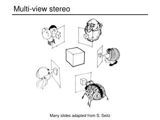
Multi-View Drawing Review. Sacramento City College EDT 300/ENGR 306. Objectives. Identify and select the various views of an object. Determine the number of views needed to describe fully the shape and size of an object. Define the term orthographic projection

E N D
Multi-View Drawing Review Sacramento City College EDT 300/ENGR 306 EDT 300 / ENGR 306 - Chapter 5
Objectives • Identify and select the various views of an object. • Determine the number of viewsneeded to describe fully the shape and size of an object. • Define the term orthographic projection • Describe the difference between first and third-angleprojection. EDT 300 / ENGR 306 - Chapter 5
Objectives • Visualize the “glass box” concept and apply it to the process of selecting and locating views on a drawing. EDT 300 / ENGR 306 - Chapter 5
Objectives • Develop a multi-view drawing, following a prescribed step-by-step process, from the initial idea to a finished drawing. EDT 300 / ENGR 306 - Chapter 5
First angle projection Front View Horizontal Plane Implementation Multi-view Drawing Negative Cylinder Normal Views Orthographic Projection Pictorial Drawing Profile plane Quadrant Right-side View Solid Model Spherical Third-angle Projection Top View Vertical Plane Visualization Vocabulary EDT 300 / ENGR 306 - Chapter 5
Communication • People communicate by verbal and writtenlanguage and graphic (pictorial) means. • Technical drawings are a graphical means to communicate. • When accuratevisual understanding is necessary, technical drawing is the most exact method that can be used. EDT 300 / ENGR 306 - Chapter 5
Visualization and Implementation • Technical drawing involves: • Visualization • The ability to see clearly in the mind’s eye what a machine, device or object looks like. • Implementation • The process of drawing the object that has been visualized. EDT 300 / ENGR 306 - Chapter 5
Visualization and Implementation • A technical drawing, properly made, gives a clearer, moreaccuratedescription of an object than a photograph or written explanation. EDT 300 / ENGR 306 - Chapter 5
Visualization and Implementation • Technical drawings made according to standard rules result in views that give an exact visual description of an object. • The multi-view drawing is the major type of drawing used in the industry. EDT 300 / ENGR 306 - Chapter 5
Multi-View Drawing • A photograph can show three views • Front. • Top. • RightSide. • Nearly all objects have six sides, not three. EDT 300 / ENGR 306 - Chapter 5
Multi-View Drawing EDT 300 / ENGR 306 - Chapter 5
Multi-View Drawing • If an object could be shown in a singlephotograph, it would also include • A left-side view. • A rear view. • A bottom view. EDT 300 / ENGR 306 - Chapter 5
Pictorial Drawing • An object cannot be photographed if it has not been built (!) • This limits the usefulness of photographs to “show what an object looks like” (!) EDT 300 / ENGR 306 - Chapter 5
Pictorial Drawing • A pictorial drawing • Is a drawing. • Shows an object as it would appear in a photograph. • Shows the way an object looks, in general. • It does not show, the exact forms and relationships of the parts that make up the object. EDT 300 / ENGR 306 - Chapter 5
Pictorial Drawing • A pictorial drawing • Shows the object as it appears, not as it really is. • Holes in the base appear as ellipses, not as true circles. EDT 300 / ENGR 306 - Chapter 5
Pictorial Drawing Photograph Pictorial Drawing EDT 300 / ENGR 306 - Chapter 5
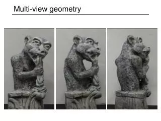
Multi-View Drawing • The goal, is to represent an objecton a sheet of paper in a way that described its exact shape and proportions. • To do this: Draw views of the object as it is seen from different positions. EDT 300 / ENGR 306 - Chapter 5
Multi-View Drawing • These views are then arranged in a standard order. • Anyone familiar with drafting practices can understand them immediately. EDT 300 / ENGR 306 - Chapter 5
Multi-View Drawing • To describe accurately the shape of each view imagine a position • Directly in front of the object. • Directly above the object. • On the right side of the object. EDT 300 / ENGR 306 - Chapter 5
Multi-View Drawing • The front, top and right side views are the ones most often used to describe an object in technical drawing. • They are called the Normal views. EDT 300 / ENGR 306 - Chapter 5
The Relationship of Views • Views must be placed in proper relationship to each other. • The Top View is directly above the Front View • The Right-side View is directly to the right of the Front View. EDT 300 / ENGR 306 - Chapter 5
The Relationship of Views • When the views are placed in proper relationship to one another, the result is a multi-view drawing. • Multi-view drawing is the exact representation of an object on one plane. EDT 300 / ENGR 306 - Chapter 5
The Relationship of Views • Other views may also be required. • The proper relationship of the six views is shown below “Normal views” Top View Left-side View Front View Right-sideView RearView Bottom View EDT 300 / ENGR 306 - Chapter 5
V-Block EDT 300 / ENGR 306 - Chapter 5
Orthographic Projection • These views are developed through the principles of orthographic projection • Ortho - “straight” or “at right angles”. • Graphic - “written” or “drawn”. • Projection - from two Latin words: • Pro, meaning “forward” • Jacere, meaning “to throw” • The literal meaning is “thrown forward, drawn at right angles”. EDT 300 / ENGR 306 - Chapter 5
Orthographic Projection • Definition: Orthographic projection is: • the method of representing the exactform of an object • in two or more views • on planes usually at rightangles to each other, • by lines drawn perpendicular from the object to the planes. EDT 300 / ENGR 306 - Chapter 5
Orthographic Projection • An orthographic projection drawing is a representation of the separate views of an object on a two-dimensional surface. • It reveals the width, depth and height of an object. EDT 300 / ENGR 306 - Chapter 5
Orthographic Projection EDT 300 / ENGR 306 - Chapter 5
Angles of Projection EDT 300 / ENGR 306 - Chapter 5
Angles of Projection • On a technical drawing, a plane is an imaginary flat surface that has no thickness. • Orthographic projection involves the use of three planes. • Vertical plane. • Horizontal plane. • Profile plane. • A view of an object is projected and drawn on each plane. EDT 300 / ENGR 306 - Chapter 5
Angles of Projection • The vertical and horizontal planes divide space into four quadrants (quarters of a circle). • In orthographic projection, quadrants are usually called angles. • Thus we get the name, first-angle projection and third angle projection EDT 300 / ENGR 306 - Chapter 5
Angles of Projection • First angleprojection is used in European countries. • Third angleprojection is used in the US and Canada. • Second and fourth angle projection is not used. EDT 300 / ENGR 306 - Chapter 5
First Angle Projection • First angleprojection • Front view = vertical plane. • Top view = horizontal plane. • Left side view = profile plane. EDT 300 / ENGR 306 - Chapter 5
First Angle Projection • In first angle projection, the Front View is located above the Top View. • The Left-side View is to the right of the Front View. • Refer to Figure 5-12. EDT 300 / ENGR 306 - Chapter 5
First Angle Projection • In first-angle projection, the projection plane is on the far side of the object from the viewer. • The view of the object are projected to the rear and onto the projection plane instead of being projected forward. EDT 300 / ENGR 306 - Chapter 5
Third Angle Projection • Third angleprojection • Front view = vertical plane. • Top view = horizontal plane. • Right side view = profile plane. EDT 300 / ENGR 306 - Chapter 5
Third Angle Projection • In third angle projection, the Top View is located above the Front View. • The Right-Side View is to the right of the Front View. • Refer to Figure 5-14. EDT 300 / ENGR 306 - Chapter 5
Third Angle Projection • In third-angle projection, the projection plane is considered to be between the view and the object, and the views are projected forward to that plane. EDT 300 / ENGR 306 - Chapter 5
Third Angle Projection • The views appear in their natural positions when the views are revolved into the same plane as the frontal plane • The top view appears above the front view. • The right-sideview is to the right of the front view. • The left view to the left of the frontview. EDT 300 / ENGR 306 - Chapter 5
The Glass Box EDT 300 / ENGR 306 - Chapter 5
The Glass Box • In each case the three views have been developed by using imaginarytransparent planes. • The views are projected onto these planes. EDT 300 / ENGR 306 - Chapter 5
The Glass Box • Visualize a glass box around the object • Project the view of the object onto a side of the box. • “Unfold the box” to one plane. • The views will be in their relative positions. EDT 300 / ENGR 306 - Chapter 5
The Glass Box EDT 300 / ENGR 306 - Chapter 5
The Glass Box EDT 300 / ENGR 306 - Chapter 5
Projection of Lines EDT 300 / ENGR 306 - Chapter 5
Projection of Lines • There are four kinds of straight lines found on objects in drawings • Horizontal. • Vertical. • Inclined. • Oblique. • Each line is projected by locating its endpoint. EDT 300 / ENGR 306 - Chapter 5
Horizontal Lines • Horizontal lines • Are parallel to the horizontal plane of projection. • Are parallel to one of the planes. • Are perpendicular to the third plane. • Appear as true length in two of the planes. • Appear as a point in the third. EDT 300 / ENGR 306 - Chapter 5
Vertical Lines • Vertical Lines • Are parallel to the frontal plane. • Are parallel to the profile plane. • Are perpendicular to the horizontal plane. • Appear true length in the frontal and profile planes. • Appear as a point in the horizontal plane. EDT 300 / ENGR 306 - Chapter 5
Inclined Lines • Inclined Lines • Are parallel to one plane of projection. • Are inclined in the other two planes. • Appear true length in one of the planes. • Appear shortened in the other two planes. EDT 300 / ENGR 306 - Chapter 5
Oblique Lines • Oblique Lines • Are neither parallel nor perpendicular to any of the planes or projections (!) • Appear shortened in all three planes of projection. EDT 300 / ENGR 306 - Chapter 5