Download
1 / 25
250 likes | 253 Views
Overview of the Intra-Bunch Train Feedback (IBFB) system for the European XFEL, including its design, components, and capabilities.

E N D
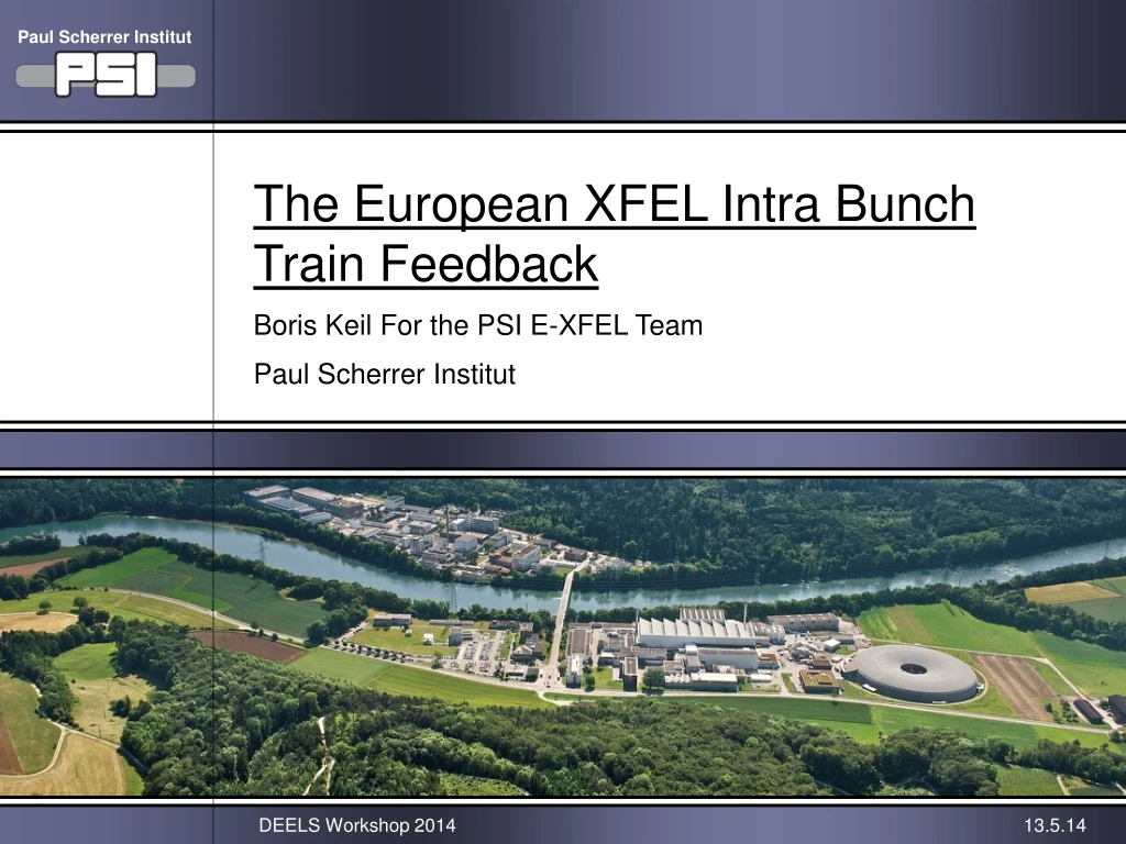
Paul Scherrer Institut The European XFEL Intra Bunch Train Feedback Boris Keil For the PSI E-XFEL TeamPaul Scherrer Institut DEELS Workshop 2014 13.5.14
IBFB E-XFEL IBFB Overview • Low-latency (~1μs) beam position correction upstream of beam distribution. • Can kick each bunch individually, using feedback + feed-forward algorithm. • Uses undulator BPM data (latency 5-10μs) for fine-tuning of undulator orbit • (to correct kicks between IBFB and undulators: Vibrations, distribution kicker, ...).
Transverse Perturbations • IBFB kickers should provide enough kick to correct perturbations, plus reserve. • IBFB removes perturbations, but also adds noise to the beam (dominated • by BPMs): Noise should not have negative impact on FEL performance • → Low-noise BPMs (goal: <1μm RMS). Pickups: 3.3GHz cavity, same as TL. • Feedback loop latency <1.5μs expected to be sufficient. *Worst-case estimate (DESY), 30m beta function at kicker & BPM, adding of peak values.
IBFB Kicker Magnet • 50 Ohms stripline kicker (picture shows cut / only half). • Kicker design by PSI (based on CTF3/Daphne design by F. Marcellini et al., • INFN Frascati), supported by DESY (wakefield simulations, M. Dohlus). • Tapered 2m long strips. • Wakefield simulations: Kicker vessel needs no taper. • Prototype built by company COMEB, RF test successful. • DESY uses modified version (aperture, ...) for dump kickers. Flexible RF feedthrough Ceramic spacers & RF feedthroughs allow thermal expansion of strip relative to vessel (bakeout, tolerances, ...) Aluminum vessel and strips (low weight, easy to fabricate) DESY standard steel flanges
Kicker Positions & Beam Optics Reserved space for upgrade: Double number of kickers and max. kick Baseline: 4 Kickers of 2m length for IBFB. Dump kickers
IBFB Kickers: RF Power Amps • Commercial amplifiers from Company TOMCO (class AB solid state). • Improved at request of PSI: Redundant power supply & amp modules • to maximize MTBF. • Two amplifiers purchased & tested extensively: Meet PSI specifications. • Kick: > ±4μrad baseline (4 kickers), > ±8μrad upgrade (8 kickers). Two Amplifiers Two Amplifiers
IBFB Kickers: RF Power Amps TOMCO guarantees 3kW pulse power, but amp reached 6kW! Prototype test at PSI: IBFB will most likely use 18MHz amplitude-modulated sine or square wave.
IBFB Kickers: RF Power Amps Droop of kick voltage over bunch train (thermal effects in MOSFETs, ...): IBFB digital electronics will compensate droop
IBFB: Electronics Topology Feedback/Feed-forward algorithm: Same FPGA board as BPMs, but with 0.5-1GSPS DAC mezzanine to generate kicker waveforms
IBFB: Algorithm • Ultra-fast feedback removes random perturbations, e.g. beam offset of • whole bunch train due to mechanical vibrations etc. • Adaptive feed-forward corrects reproducible perturbations that are the • same for each bunch train (or change very slowly). • IBFB can use same FPGA carrier board as BPMs. Present version (Xilinx Virtex-5 • FPGA, PowerPC) sufficient, new version (Artix-7/Kintex-7 FPGAs + DSP) • under development, will simplify development of more complex algorithms for • future operating modes.
IBFB: Cavity BPM Pickups Prototype at SwissFEL Injector Test Facility • Transfer Line Cavity BPM • 3.3GHz, 40.5mm aperture. • Used for: Transverse intra-train • feedback, energy measurements, • launch jitter control & correction • (energy, BAM, linac entry, …), • optics measurements, … 255mm Similar to undulator type, slightly less resolution (~20%). Main differences: ~16x more angle signal (→ align 16x better), cavity spacing (→ crosstalk). D. Lipka DESY
IBFB: Cavity BPM Electronics New: 63dB range, 0.5dB steps MBU Crate: Removable fan tray, redundant main power supply, ... RFFE DOOCS & Timing Interface (SFP/Optical, PCIe/Ethernet/..., up to 6.5Gbps) Differential coax cabling from RFFE to ADCs • I/Q downconversion to baseband. • Active temperature stabilization (several sensors + heaters). • Works with or without external trigger & ref. clock.
ADC Sample Clock Phase Feedback Digital ADC sampling clock phase alignment loop • Eliminates phase drift effects • Retains maximal S/N ratio • Monitors possible reference signal malfunctions & beam arrival time changes Present algorithm: Uses just one ADC sample at top to calculate beam position.
Cavity BPM ElectronicsTemp. Drift Temperature drift scales with beam offset. Active temperature stabilization active: <100nm/°C drift at 1mm offset (0.01%/°C)
GUI For Automated Lab Calibration • Presently using commercial RF generator (pulsed) for automated lab calibration (gain & phase delay for each attenuator setting; IQ imbalance, ...). • Developing low-cost test/calibration system (external "customers", ...).
SwissFEL BPM Test Area Correlation of 3 E-XFEL Undulator Cavity BPMs Sampled RFFE IQ Signals Only top sample used (so far ...), plus baseline subtraction Histogram (X1+X3)/2 – X2 See IBIC’12, TUPA27, M. Stadler et al.
IBFB: Cavity BPM Performance • Position Noise (RMS, 1 Bunch) • Undulator cavity (Ø=10mm): • ~11μm @ 2pC (±5mm range) • <0.5μm @ 100-1000pC (±1mm range) • Transfer line cavity (Ø=40.5mm): • ~1μm @ 100-1000pC (±1mm range) 2x improvement feasible by digital removal of angle signal (15x bigger than for undulator BPMs) – work in progress ... 20mm offset at 1nC: 50V signal! RFFE may need input protection via attenuator (4x worse low-charge resolution), or extra protection circuit (to be developed for IBFB) • Charge Measurement RMS Noise (1 Bunch) • Undulator cavity (Ø=10mm): • <0.06% @ 100-1000pC • <60fC @ 100pC • <10fC @ 2pC
IBFB Status • IBFB BPMs (Will Dominate IBFB Performance ...) • Using standard E-XFEL cavity BPM electronics (maybe • with external RFFE input protection circuit (1nC & big beam • offsets ...), necessity being investigated). • IBFB (Non-BPM) Electronics Hardware • Can use BPM FPGA carrier board also for IBFB signal processing. • DAC mezzanine to driver kicker amps under development. • IBFB Firmware/Software • Feedback/Feed-forward algorithm & feedback network via • multi-gigabit fiber optic links to be implemented (re-using • building blocks from BPM firmware/software).
Team & Acknowledgements • PSI: • M. Stadler (Cavity BPM RF front-end) • M. Roggli, M. Gloor (ADC/DAC Mezzanine) • R. Baldinger, D. Engeler (FPGA carrier board HW) • G. Marinkovic, W. Koprek (Firmware & software) • C. Beard, F. Marcellini, M. Rohrer, D. Treyer, (IBFB kicker magnet • & RF power amps) • DESY: • S. Vilcins, D. Lipka, D. Nölle (Cavity BPM pickup) • M. Dohlus (Kicker wakefield simulations) • N. Golubeva, W. Balandin, W. Decking (Magnet lattice & beam optics) • ... and all other supporters at PSI & DESY/E-XFEL
Paul Scherrer Institut Thank you for yourattention!