Download
1 / 37
370 likes | 542 Views
ABCN&HCC Status. AUW 2011 CERN ABCN&HCC 130 nm Development. Joel de Witt, University of Santa Cruz, California. M. Newcomer, N. Dressnandt , University of Pennsylvania. Matt Warren, Samer Kilani , UCL. Michelle Key- Charriere , RAL. D. La Marra , University of Geneva.

E N D
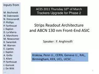
ABCN&HCC Status AUW 2011 CERN ABCN&HCC 130 nm Development • Joel de Witt, University of Santa Cruz, California. • M. Newcomer, N. Dressnandt, University of Pennsylvania. • Matt Warren, SamerKilani, UCL. • Michelle Key-Charriere, RAL. • D. La Marra, University of Geneva. • F. Anghinolfi, J. Kaplon, CERN. • W. Dabrowski, K. Swientek, AkademiaGórniczno-Hutnicza, Krakow. CERN AUW Week
iTK-SC Stave or Module 128 ch ABCN 250 FE ASIC Back-end Tail (Signals, Power) Actual Stavelet Status (4 detectors, 8 hybrids, 160 ABCN) CERN AUW Week
iTK-SC Stave or Module Develop 256 ch. 130nm CMOS FE chip (ABCN 130) Develop 130nm CMOS Hybrid Controller chip (HCC) CERN AUW Week
HCC Controller Chip 1.2V operation 130nm Process Hybrid (ABC130) side HybridController St_Clk CMD_BC PLL BCABC Beam Clock BC/L1 phase CMD_L0 Bussed Signals on Hybrid ABC Cmd LCL Cmd SR / Setup DCS RO Service side L0_L1 R3s_L1 R3 DRC Data Readout Clock DataI One serial Loop Xon/off Data Concentrator FiFo Data Loop Data/CLK Encode Xon/off DataII Data Loop Hybrid @ bits DCS Data I and Data II are separately enabled redundant outputs to the same Stave bus data pair. V(temp), V(analog) CERN AUW Week
HCC – ABC130 chip LVS communication 10 ABCN IN A ROW Hybrid Controller Chip ABC130 Chip ABC130 Chip Programmable current drive (4-bits) BC (Beam Clock 40MHz) Hybrid Controller BC 320 MHz St_Clk DLL CMD_L0 CMD_L0 CMD_BC BC/L1phase R3s_L1 R3s_L1 ABCCmd LCLCmd SR/Setup DCSRO CORE L0_L1 DRC (Data Readout Clock 160MHz) Drivers Delay ~1ns Receivers Delay~2.5ns DRC Receivers R3 Data: 160Mbits/s) DataI Xon/off Programmable delay adjust FIFO / Data Concentrator Data Loop Xon/off Data/CLKEncode DataII One serial Loop Direction (1-bit) Data Loop Xon / Xoff Hybridbits Programmable current drive (4-bits) Direction (1-bit) DCS Programmable current drive (4-bits) Bidirectional Transceivers 160MHz Enable (1-bit) in in in in in in in in in in in in CERN AUW Week Enable (1-bit) out out out out out out out out out out out out
ABCN 130 nm – Simplified block Diagram Adjacent chip Top_Logic Front End x256 Comparators L1_DCL ReadOut Block L0_Buffer R3L1_Buffer R3_DCL Detector pads: 256 input pads Command Decoder Serial interface COM/L0 R3/L1 2 Levels of buffering R3 (local readout, fast) L1 (full readout, slow) Serves 2 rows of 128 x 2cm strips ABCN level block diagram. CERN AUW Week
Buffer Size • Buffers sizing L0 Latency “L0 Buffer (Pipeline)” 256 time slots = 6.4us max L1 (R3) Latency “R3L1 Buffer” 256 events (768 Time slots) @ 1MHz Write rate = 256 us max CERN AUW Week
ABCN130 Read Out Module READOUT Priority Reg Local FiFO High nn nn Local MUX & Priority setting DCL R3 Local FiFO Thru MUX & Priority setting 51 51 Thru DataOut (59 bits DataPacket) 51 SERIALIZER Priorityorder + Typ(4) + ChipID(4) + Header(1) + Last bit (1) Local FiFO DCL L1 51 51 Control Status DCS Local FiFO Data Packet To next chip nn nn Low 1x118 bits Thru DataIn 1 thruFIFO Data Packet from adjacent chip CERN AUW Week
ABCN 130nm : 59-bit data packet per chip 4 clusters central hit position Event ID 3 clusters geom. patterns CERN AUW Week
Functional Code & Simulation Test Bench:SVN Repository Structure SVN | ----------------------------------------------------------------------------------------------------------------- | | | ABCNHCCTRIPLICATION --------------------|------------------------------------------------------------------------------ | | trunkbranches | | -------------------------------------------------------------------------------- USC development branch | | | rtlscriptstest ------- --------- ----------------------------------------- | | | | L0_L1_Buffer simulation scripts matlab TEST_BENCH R3_DCL | L1_DCL ------------------------------------ ReadOut | | Top_Logic Post Processing v3 commandController | | | integration DCL ReadOut Test vector generation CERN AUW Week Slide Courtesy : Michelle Key-Charriere/RAL
Simulation test benches ABCN13.v Makefile (run simulation) //`include "timescale.inc" `timescale 1ns/1ps module ABCN13 ( //bottom edge signals CLK_padP, CLK_padN, BC_padP, BC_padN, COM_LZERO_padP, COM_LZERO_padN, LONERTHREE_padP, LONERTHREE_padN, RST_padP, RST_padN, ID, //data from the detector DIN, //left edge signals XOFFL, XOFFLB, DATL, DATLB, //right edge signals XOFFR, XOFFRB, DATR, DATRB ); #SIM_OPTS = +define+logThruFIFODEPTH=4 +define+logLocalFIFODEPTH=5 +define+logCSRFIFODEPTH=3 +define+PACKETWIDTH=54 +define+PW=53 #customer didn't like this approach??? #for vcs sim, no gui #VERILOG = vcs #for ncverilog sim, simvision #add +ncsimargs+-gui +gui_sync to COMMON_DEFINES if gui-driven simulation is desired #change +access+r to +access+w to COMMON_DEFINES if SEU test scripts has to be run VERILOG = ncverilog COMMON_DEFINES = +define+TEST=test +define+TB=tb +access+r VLOG_OPS = +v2k +libext+.v VLOG_LIBS = -y ../rtl/ABCNmodules -y ../rtl/TBmodules -y ../../trunk/rtl/Pipeline_InReg -y ../rtl/Top_Logic -y ../../trunk/rtl/L1_DCL -y ../../trunk/rtl/R3_DCL -y ../../trunk/rtl/L0_L1 -y ${IBM_PDK}/ibm_cmos8rf/std_cell/relDM/verilog -y ${IBM_PDK}/ibm_cmos8rf/short_io/relDM/verilog -y ../../trunk/rtl/WatchDog TOP_MODULES = ../rtl/ABCNmodules/ABCN13.v ../../trunk/rtl/L0_L1/veri_globals_v2.v ../../trunk/rtl/L0_L1/pipecontrollerandL0ID.v ../../trunk/rtl/L0_L1/ROAddressSelect.v #GATE_LEVEL_MODULES = commandControl.vg readOut.vg readReg.vg #GATE_LEVEL_MODULES = ../rtl/synthesized_rtl/reg32.vg TEST_COMPONENTS = ${VERILOG} ${VLOG_OPS} ${VLOG_LIBS} ${COMMON_DEFINES} ${TOP_MODULES} ${GATE_LEVEL_MODULES} #these are verilog simulation targets for development/experimental tests. #log files are produced but self-checking does not occur. #f(CLK)/f(BCCLK)=4 TB1_DEV_TESTS = tb1test0 tb1test1 tb1RegTest tb1InputRegTest tb1PipeLineL1 tb1PipeLineR3 CERN AUW Week Top Level and Makefile by Joel de Witt/UCSC
Cadence IC6 Simulation Environment Packets transmitted Serial data logged to file for post processing CERN AUW Week Slide Courtesy : Michelle Key-Charriere/RAL
Matlab Post Processing Scripts • To check the accuracy of the data transmission, run the post processing script: .\abcnasic\abcn\trunk\test\Matlab\PostProcessing\ReadOut\packet_analyser.m >> packet_analyser All of the loop 1 packets were recovered successfully. Percentage packet loss (%):0 All of the loop 2 packets were recovered successfully. Percentage packet loss (%):0 • A bit level verification script for the Data Compression Logic (DCL) is available: .\abcnasic\abcn\trunk\test\Matlab\PostProcessing\DCL\DCL_verification.m • This requires the matlab models L1_DCL.m and R3_DCL.m to be ‘bit true’ relative to the verilog implementations of the L1_DCL and R3_DCL blocks More work is required to complete this verification tool. CERN AUW Week Slide Courtesy : Michelle Key-Charriere/RAL
Data Packet Analyzer Chip 2 Packet-Type=1000 SEU-Flag=0 Register-Address=20 CSR=00000f01 Chip 2 Packet-Type=1000 SEU-Flag=0 Register-Address=23 CSR=00000005 Chip 2 Packet-Type=1000 SEU-Flag=0 Register-Address=22 CSR=00000002 Chip 2 Packet-Type=0010 Trigger-ID= 0 Bunch-ID= 89 C1: add= 0 C2: add= 0 C3: add= 0 C4: add= 0 Ovfl=0 Chip 2 Packet-Type=0011 Trigger-ID= 1 Bunch-ID=169 C1: add=254 C2: add= 0 C3: add= 0 C4: add= 0 Ovfl=0 Chip 2 Packet-Type=0011 Trigger-ID= 2 Bunch-ID=181 C1: add=253 C2: add= 0 C3: add= 0 C4: add= 0 Ovfl=0 Chip 2 Packet-Type=0011 Trigger-ID= 3 Bunch-ID=193 C1: add=252 C2: add= 0 C3: add= 0 C4: add= 0 Ovfl=0 Chip 2 Packet-Type=0110 Trigger-ID= 1 Bunch-ID=169 C1: add=255 bits=000 C2: add=255 bits=000 C3: add=255 bits=000 Chip 2 Packet-Type=0110 Trigger-ID= 2 Bunch-ID=181 C1: add=254 bits=000 C2: add=254 bits=000 C3: add=254 bits=000 Chip 2 Packet-Type=0110 Trigger-ID= 5 Bunch-ID=217 C1: add=248 bits=000 C2: add=248 bits=000 C3: add=248 bits=000 Register Read R3 L1 1 event empty 2nd event 1 hit @ channel 255 3rd event 1 hit @ channel 254 4th event 1 hit @ channel 252 5th event 1 hit @ channel 248 Read R3 Events 0 1 2 Read L1 Events 1 2 5 Read R3 Event 3 Commands CERN AUW Week
Overall layout 7.5 mm • Max width 7.5 mm • FE pads • Only and no GND pads alongside • Span as wide as chip • Data/Token • Chip-to-chip on air • Return pair underneath • 4 pairs of traces to MCC • Clock, command, etc. on side • Bus traces underneath • Maximizing spacing between pairs, no redunancy • Ground, power and chip ID on bottom • In the next pages, discuss the FE pads and pads to hybrid… FE bonds only (4 rows of 64) Token and Data (2 pairs) Token and Data (2 pairs) BCO, L1, Com, Clk, Reset (5 pairs) Ground, Power, Chip ID CERN AUW Week Slide Courtesy : Y. UNNO/KEK
Front End • Would like FE bond pads to take full width of ASIC • Ground pads if needed below FE connections • Ground pads would have to bond to the side, use same pad shape as for BE • Would like ~50x200 mm pads with 100 mm spacing between rows 200 mm 100 mm 1100 mm Ground (if needed) CERN AUW Week Slide Courtesy : A. Greenhall/Liverpool
Simple ideas and proposals • Assumptions based on : • Tentative to limit the triplications where strictly needed • In criticality order “ABCN 130”SEU strategies CERN AUW Week
S. Bonacini CERN Double DFF with interleaved subblocks to separate redundant nodes (IBM standard cell type layout currently under development, Filipe Sousa) Dice Cell 4.5um The DICE cell may be an “easy” and power effective way to protect efficiently against SEU most part of the circuit CERN AUW Week
IRRADIATIONS PLANS • Front-End Prototype • Xray at low temperature • Low dose rate irradiation • “Beam” hit test vs. special ESD protection (P) • RAM block SEU cross section (P) • SEU standard Logic cross section (with and w/o TRM) (Going on) CERN AUW Week
ABCN Front-End Prototype 32 channels Layout 10 channels access Jan Kaplon (Design)/Matt Noy (Measurements) Full set of measurements in backup slides CERN AUW Week
Noise performance Markers show measured data points, lines are theoretical calculations No excess noise visible (Γ excess noise factor equal to 1). CERN AUW Week
Fast Track Trigger Optionin ABCN Slides by Mitch Newcomer CERN AUW Week
Trigger Primitives for Commissioning & Innovation Challenge: Provide cluster information within a few BC of Event Time to seed first level trigger beam syncronous trigger with high PT track enhanced triggers. Event Time This kind of prompt trigger was quite useful during commissioning of the TRT and for triggering the Inner Detector after the LHC accident. fixed Latency ~6-10µS BC Syncronous L0 CERN AUW Week
IT-SCFast Clustering Conceptual Block Diagram 256 Channel Analog Front End Data Pipeline Pipeline Data out BC Data from Pipeline Input 128 Strips 128 Strips Bank 1 Data Bank 2 Data Cluster ? Cluster ? Separately enabled block • Store Data as two banks of 128 strips at BC time. • One buffer register per bank. • Perform clustering algorithm in multiple steps @ 160Mhz • using tightly restricted acceptance rules (next page) • Send Fixed Length Cluster information at a fixed #BC (4) after the • event to each dedicated LVDS output. • Due to low strip occupancy it is allowable to allocate several BC • each time a cluster is located. CERN AUW Week
Proposed ABC130 Powering Options • 1 single power domain for hybrid • No DC/DC on chip Analog Front End (1) RC filter Digital Core ABC130 Analog 1.2V LDO Digital Variable LDO (1) Dig LDO In An LDO In Vref Dig RC filter (2) (2) CERN AUW Week
ABCN 130 Status • Progress on specs • Functional model and simulation test bench on going • Digital Synthesis has started • FloorPlan will start soon, incl RAM block developed by CERN/PH/ME • SEU protections to be finalized • Issues on STD CELLS (Dice?) CERN AUW Week
HCC Status • Specifications on going • Resources for code development are well defined for the coming year • Resources for Floorplan/Final Layout have still to be defined • Co-submission with ABCN 130 planned for End Q3-2012 CERN AUW Week
Backup Slides CERN AUW Week
Matching of the front end gains Mean 83 – 88mV/fC RMS 3 – 4mV/fC CERN AUW Week
Matching of discriminator offsets Mean ~ 0mV RMS 8 – 13mV Pk-Pk value < 80mV With 5 bit DAC the step will be 1.5 – 2 mV (gain 85 mV/fC) CERN AUW Week
AC parameters of the input stage • Input transistor bias 80uA • Cross talk signal is less than 3% for detector capacitance 1.5 pF to bulk + 2x 1.6 pF to neighbor CERN AUW Week
Parameters of the full chain Time walk defined for signals 1.2 and 10fC with discriminator threshold set to 1fC. CERN AUW Week
Command Packet Command Decoder CERN AUW Week 53 bits
ABCN 130 nm – Block Diagram Readout L1 latency (up to 500us ?) L0 latency (6.4us) DCL L1 Local FiFO 20 256 Pipeline (SRAM) 256 256 L1 buffer (SRAM) WA RA WA RA Local FiFO DCL R3 256 L0ID 20 BC WAgen RAgen At BC : WA=WA+1 At L0: RA=WA-L0Lat R Event Address R Event Address R3 L1 CLK RR RR Data Flow Control Command Decoder W W L0-COM R3L0ID L1L0ID R3-L1 BC CERN AUW Week
(L0Buffer, pipeline) Expected 264 bw x 256 al will translate into 5 times 64 bw (320 bits) and 2 times al (256 depth) Size : 5 x 150um in Y and 900um in X : 0.9mm x 0.75mm ABCN Design Picture 0.9 mm Unit size : 450x 150 um 128 addresses in X and 64 word bits in Y 0.75mm L0 pipeline : 320 bits word by 256 addresses 82Kbits memory CERN AUW Week
(L0ID Buffer) Expected 272 bw x 728 al will translate into 5 times 64 bw (320 bits) and 6 times al (728 depth) Size : 5 x 150um in Y and 2700um in X : 2.7mm x 0.75mm ABCN Design Picture 2.7 mm 0.75mm L0ID Buffer : 320 bits word by 728 addresses 233Kb memory CERN AUW Week
GBTX Hybrid readout through the GBT system HCC 12 HCC 6 HCC 1 E-link 1 – 80-160MHz-clk E-link 2 – RXDATA : COM E-link 3 – RXDATA : L0/L1 E-link 4 – RXDATA : R3 E-link 1 – TXDATA (80MHz) E-link 6 – TXDATA (80MHz) E-link 12 –TXDATA (80MHz) HCC 24 HCC 18 HCC 13 E-link 1 – 80-160MHz-clk E-link 2 – RXDATA : COM E-link 3 – RXDATA : L0/L1 E-link 4 – RXDATA : R3 E-link 13 – TXDATA E-link 18 – TXDATA 1 per hybrid E-link 24 – TXDATA CERN AUW Week