Download
1 / 32
320 likes | 438 Views
NETWORK LAYER FEEDBACK ENABLED ADAPTIVE APPLICATION-LEVEL REROUTE. by Liping Guo Gouri Landge. Agenda. Motivation Proposed NLFEALR-scheme A simple simulation system Realization of NLFEALR & MDC-PD Results & Comparison Conclusion Q&A. Motivation. Undesirable network condition:

E N D
NETWORK LAYER FEEDBACK ENABLED ADAPTIVE APPLICATION-LEVEL REROUTE by Liping Guo Gouri Landge
Agenda • Motivation • Proposed NLFEALR-scheme • A simple simulation system • Realization of NLFEALR & MDC-PD • Results & Comparison • Conclusion • Q&A
Motivation • Undesirable network condition: • Two major causes for packet-loss over the Internet: Congestion & Link/node failure. • Link/node failure happens due to faulty equipment, router misconfigurations, and fiber cuts… • Long transient period for link failure: single domain-tens of seconds; inter-domain-several minutes. • What if nothing is done for the transient period?
Motivation (cont.) • How to deal with it? • Multiple Description Coding (MDC) with path diversity (MDC-PD) • creates independently decodable representations of the video and transmitting them on different routs. • Tradeoff between compression performance and error resilience • What if link failure happens only infrequently?“Overprotection” ! ! !
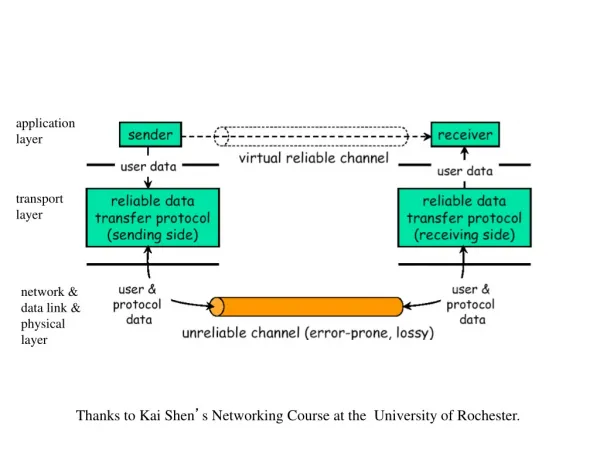
Motivation (cont.) • Goal: avoid “overprotection” and achieve efficient use of the network resources. • How? Adaptive reroute “on the fly” • Fast link failure feedback is essential!!! • Good news: Network Layer Feedback System (NLFS) proposed in: R. Keralapura, C. N. Chuah, M. van der Schaar, C. Tillier, an B. Pesquet-Popsecu, “Adaptive Multiple Descriptions Scalable Video Coding Using Network Layer Feedback.”
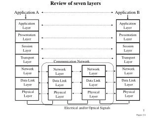
Network Layer Feedback System (NLFS) R. Keralapura et al. • Video server needs to register with the nearest “Overlay Broker” before starting a video session. • Synergy Layer is created on top of the IP layer and deployed in every router in various domains to provide feedback. • Link failure info (e.g. IP addr of failed node) is passed to the server through the overlay broker. • The maximum feedback delay is approximately 0.26 second.
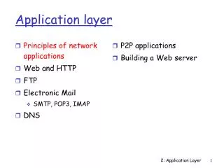
Adaptive Application-level Reroute (1) Routing components - Routing table-like structure is maintained by each media server; it contains info about all possible backup paths. - Loose Source Record Route (LSRR) is used to do reroute. (2) Rate adaptation component The focus of our project !
Rate adaptation componentHow did we look at the problem? • Assume playback starts after 2 second buffering; • Once play back starts, buffer enters “equilibrium status”: the number of frames in the buffer is constant (avg); • Link failure breaks the buffer’s equilibrium status; in worst case, buffer could be overplayed to empty; severe video quality degradation at the receiver side. • Find a way to let the play out buffer recover its equilibrium status fast… How? Send more with less quality
Rate adaptation componentHigh quality to low quality switch Synchronization control @ server
Rate adaptation componentWhat bit rate to switch to? • Toc: buffer over-consume time includes failure feedback delay (max 0.26s), routing process time (Tp), and 1/2 RTT.
Rate adaptation componentLet’s do the math! • Noc: number of over consumed frames during Toc (s). • Rn: newly adapted streaming bitrate. (kbps) • Bn: available bandwidth of the chosen backup path. • Rp: play rate at the receiver side. • Qn: quality of the newly adapted video stream. (kbpf) • Rn = Rp * Qn Assume refill buffer overrun portion within 1 second (2) Qn = Bn / (Rp *1s + Noc) (3) Noc = Rp * Toc (4) Toc = 0.26s + Tp + ½ RTT
Rate adaptation componentAn example bitrate switch table Server maintains the bitrate switch table Quality of video (consumption rate in bits)
Codec: IBMCTF Hinting file parser Hinting file modifier A simple simulation system
A simple simulation systemAn example packet description in a hinting file % PACKET_NUM=20 6 % TRANSMIT_SUCCESS 1 % IDENTIFICATION_TAGS # Type GOPnum Fr_Typ Tlev Pos Res Ch Chunk SubChunk 0 1 0 4 0 0 0 0 2 % DEPENDENCIES 4 ~ 5 % PACKET_SIZE 762 % IN_STREAM_POS 2000
Simulation System • Assumptions • Link Bandwidth: 768 kbps • Average Link Failure Feedback Delay: 0.26 Sec • Routing process time: 0.04 Sec • Round trip time (RTT): 150 m Sec • Video Playback Rate: 30 Frames/Sec • Buffering time: 2s * 30f/s= 60 frames • Input • 288 Frames of Akiyo Sequence at cif resolution
Realization of Rate Adaptation • Assumption • Available Bandwidth of Backup Path: 768 kbps • The Over Consumed Frames Refilled in 1 Sec • Toc = Tfb+ Tp+ ½ RTT = 0.26s + 0.04s + ½(0.15s) = 0.38s • Noc = Rp * Toc = 30fps * 0.38s = 11 frames • Qn = Bn / (Rp * 1 + Noc) =768kbps/(30+11) frames = 18.73 kbpf • Rn = Rp * Qn = 30 fps *18.73kbpf = 562(kbps)
Realization of Rate Adaptation (cont.) • PSNR at 562 kbps is calculated while decoding • To illustrate the effect of the quality adaptation, we simply replace the PSNR values of affected 41 frames, with new PSNR. • Feature can be added to the codec to be able to decode bit stream with switched bit rate. In fact, this will be needed at the receiver side, to use Rate Adaptation.
Realization of MDC-PD • Codec generated Hinting File: • The packet attributes • The status of packet transmission as seen by the receiver. • Attributes: • Texture or Motion Vector • I Frame or H Frame • Sub chunk, the packet dependency • Transmission Status • Success or Fail
Realization of MDC-PD (cont.) • Multiple Independently Decodable Descriptions • Redundant information along with each description • Error Resilience but lower quality • To achieve unequal protection • Prioritize packets by assigning different weights based on their attributes • Put most significant packets in all descriptions • Discard least significant ones to maintain BW
Realization of MDC-PD (cont.) Weight Assignment • I-Frame (Intra-coded Frame) : 400 • spatial redundancy within the frame • Independent of any other frame • Referenced by several other inter-coded frames • Loss can cause catastrophe to the decoded video • H-Frame (Inter-coded Frame) : 100 • Temporal redundancy among neighboring frames • Motion vector information • Dependent on I frame and other H frames
Realization of MDC-PD (cont.) Weight Assignment (cont.) • Temporal Level : 80 to 10 • I Frames and H Frames are further classified based on their temporal level. • Temporal levels 4 through 1 are assigned weights 80, 40, 20 and 10. • Sub Chunk Number: variable • Sub chunk number indicates the packet dependency. • Higher sub chunk number, lower significance
Realization of MDC-PD (cont.) • If cumulative weight of a packet is greater than the high threshold, add the packet to both descriptions • Equal number of packets with weight less than the low threshold is discarded. • Packets with weight between the higher and low thresholds are evenly distributed between the two descriptions such that both the streams can be decoded independently.
RESULTS & ANALYSIS (cont) • Both MDC-PD and our application-level reroute scheme improve video performance in the event of link failure. • Under normal condition MDC performance is about 1dB below the performance of Feedback Method due to Redundancy. • MDC experiences the lower PSNR for the entire duration of the transient period • Using feedback enabled reroute method, the lower PSNR is experienced only for a short duration which is independent of the transient period
CONCLUSIONS • MDC-PD provides good error resiliency • But has drawback of overprotection when network conditions are fairly stable • Feedback enabled application-level reroute scheme can be used as complementary solution for bandwidth efficiency