Download
1 / 25
260 likes | 445 Views
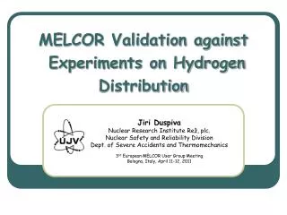
MELCOR Validation against Experiments on Hydrogen Deflagration. Jiří Duspiva Nuclear Research Institute Rež, plc. Nuclear Safety and Reliability Division Dept. of Severe Accidents and Thermomechanics 3 rd European MELCOR User Group Meeting Bologna, Italy, April 11-12, 2011. Outline.

E N D
MELCOR Validation against Experiments on Hydrogen Deflagration Jiří DuspivaNuclear Research Institute Rež, plc. Nuclear Safety and Reliability Division Dept. of Severe Accidents and Thermomechanics 3rd European MELCOR User Group Meeting Bologna, Italy, April 11-12, 2011
Outline • ISP-49 MELCOR Application • Testing of BUR Package • Flame propagation • Baby case • Problems in modeling of deflagration • Results of THAI HD-2R simulations • Summary and Conclusions 3rd EMUG Bologna, Italy, April 11-12, 2011
ISP-49 MELCOR Application NRI Participation • Main objectives • Validation of code against experiments • User experience extension to H2 deflagration topic • ISP-49 – two kinds of experiments • THAI Facility – slow deflagration • Operated by Becker Technology (Germany) • Main interest of NRI (participation in OECD THAI Project) • ENACCEF Facility – flame front acceleration • Operated by CNRS (France) • Minor interest, because MELCOR has no models for Flame Acceleration 3rd EMUG Bologna, Italy, April 11-12, 2011
ISP-49 MELCOR Application Slow Hydrogen Deflagration • OECD ISP-49 THAI Tests • No internals (only measurement) • Deflagration ignited in bottom • Homogenized atmosphere • HD-2R Test – open calculation • H2 concentration 8.0%vol. without steam; temp. 25° C; press. 1.5 bar • HD-22 Test – blind and post-blind calc. • H2 concentration 10.0%vol. with 25%vol. steam; temp. 90° C; press. 1.5 bar 3rd EMUG Bologna, Italy, April 11-12, 2011
NRI MELCOR Model Hydrogen Deflagration Tests • New input model developed for MELCOR code for OECD-THAI HD test simulation • 13 Axial levels, 7 CVs in layer(79+4 CVs, 204 FLs, and 143 HSs) • Identification of important error in burn propagation among CVs • OECD THAI data cannot be shared outside of project members Baby Case input model developed for demonstration of error to SNL developers 3rd EMUG Bologna, Italy, April 11-12, 2011
Flame Propagation Standard MELCOR 1.8.6 YT End of burn in bottom CV Next time step Stars indicate instant burns • Identification of important error in burn propagation among CVs • OECD THAI data cannot be shared outside of project members Baby Case input model developed for demonstration of error to SNL developers 3rd EMUG Bologna, Italy, April 11-12, 2011
Baby Case Nodalization Schemes • Baby case • Pipeline with ID 100 mm length 10,200 mm and wall thickness 15 mm • First part (200 mm) as space with igniter • Burning pipe with igniter space • End of deflagration should be similar in both models • 2 CVs model • Deflagration propagates from CV020 to CV050 • 6 CVs model • Deflagration has to propagate consequently from CV020 to CV051, CV052 … 3rd EMUG Bologna, Italy, April 11-12, 2011
Baby Case Results Standard MELCOR 1.8.6 YT • 2 CVs model • Deflagration initiated at t0 = 0.0 s • Propagation from CV020 to CV050 at t1 = 0.0155 s • End of deflagration in CV050 at t2 = 1.573 s • 6 CVs model • Deflagration initiated at t0 = 0.0 s • But at time t1 = 0.0155 s deflagration propagated into all remaining CVs simultaneously error in propagation algorithm • End of deflagration in all CV05i at t2 = 0.326 s 0.0 s < t < t1 t1 = 0.0155 s 3rd EMUG Bologna, Italy, April 11-12, 2011
Baby Case Results Improvement of MELCOR 1.8.6 • NRI debugging of this error resulted in identification of correction needs in two routines (burprp.f and burrun.f) • Deflagration initiated at t0 = 0.0 s End time in 2CVs model t2 = 1.573 s Standard M186 Improved M186 • Observations and modifications reported to SNL developers including Baby Case inputs (BUG Report 287) • Added refilling of burning tube with hydrogen and oxygen and initiation of subsequent deflagration second set of deflagrations again propagated into all CVs simultaneously, one more routine modified (burcom.f) to correct subsequent deflagrations 3rd EMUG Bologna, Italy, April 11-12, 2011
Flame Propagation Standard MELCOR • NRI performed set of other tests • Testing of older version (MELCOR1.8.5) against baby case with additional source of hydrogen (SNL modification) • MELGEN failed due to incompleteness of hydrogen source definition • MELGEN YT_1010 and YU_2798 do not check existence of appropriate external energy source related to external mass source as described on page CVH-UG-26 (full description in BUG339 report from end of February 2009) • MELCOR 1.8.6 (and also 2.1) corrected to fulfill request on existence of external energy source for each of external mass source • It is solved in subversion 3037 of M186 and 1191 of M2.1 • Additional testing of propagation with standard release of MELCOR 1.8.6 YT_1010 • Zero hydrogen concentration in one (or more) of CVs on propagation chain of CVs preserve remaining CVs from immediate deflagration propagation • Important for older Cntn analyses 3rd EMUG Bologna, Italy, April 11-12, 2011
Flame Propagation Improved MELCOR 1.8.6 End of burn in bottom CV Next time steps Stars indicate instant burns 3rd EMUG Bologna, Italy, April 11-12, 2011
Modeling of Deflagration Problematic Topics • Some problematic topics identified in MELCOR application to THAI HD-2R test • Significantly faster flame propagation • Flame speed determination • Remaining unburnt hydrogen • Effect of lumped parameter approach to combustion completeness • Rate of hydrogen consumed from burning 3rd EMUG Bologna, Italy, April 11-12, 2011
Modeling of Deflagration Flame Speed Determination • MELCOR uses only one correlation for all flame directions (upward, downward, and horizontal) • NRI prepared updated definition of SC2200 for application within ISP-49 • Based on OECD THAI HD tests • Proprietary source • Relevant only for upward flame propagation • It cannot be recommended for plant simulations • It played important role in HD-22 test simulation, where under-predicted flame velocity resulted in absence of deflagration in central nodes of upper half of vessel • Corrected with realistic flame velocity impact of ATM overflow 3rd EMUG Bologna, Italy, April 11-12, 2011
Modeling of Deflagration (1) Lumped Parameter Approach • Full combustion completeness is defined H2 mole fraction is 0.0 at the end of deflagration in lower CV • Continuation of deflagration in adjacent CV results in ATM pressurization in recently burning CV and its expansion overflow into all adjacent CVs • MELCOR code does not distinguish atmosphere composition in front and behind flame front position – ATM is fully homogeneous • Due to instant combustion, ATM flowing into other CVs is • H2 lean in comparison with CV in front of flame front propagation (here above) decrease of H2 mole fraction • H2 rich in comparison with CV behind flame front (here below) increase of H2 content, which remains unburnt Time = 2.465 s Time = 2.485 s 3rd EMUG Bologna, Italy, April 11-12, 2011
Modeling of Deflagration (2) Lumped Parameter Approach • Full combustion completeness is defined H2 mole fraction is 0.0 at the end of deflagration in lower CV • Continuation of deflagration in adjacent CV results in ATM pressurization in recently burning CV and its expansion overflow into all adjacent CVs • MELCOR code does not distinguish atmosphere composition in front and behind flame front position – ATM is fully homogeneous • Due to instant combustion, ATM flowing into other CVs is • H2 lean in comparison with CV in front of flame front propagation (here above) decrease of H2 mole fraction • H2 rich in comparison with CV behind flame front (here below) increase of H2 content, which remains unburnt 3rd EMUG Bologna, Italy, April 11-12, 2011
Modeling of Deflagration (3) Lumped Parameter Approach • Is it possible to find any user solution? • MELCOR has no capability to filter one or more ATM components in flow paths No • More over MELCOR does not know orientation of flame movement and position of sides – in front and behind flame front (volumetric combustion approach) • MELCOR has capability of external mass and energy sources and sinks Possible user solution • MELCOR has capability to define igniter in each of cell Possible user solution (necessary modification of some model parameters - XH2IGY, XH2CC, and XH2PDN) • Is complicated nodalization best approach for MELCOR? • More variants of nodalization prepared and tested • Some models had also subversions • Results processing focused on – timing of flame front position, pressure evolution, and unburnt mass of hydrogen 3rd EMUG Bologna, Italy, April 11-12, 2011
Modeling of Deflagration Hydrogen Removal Rate • Duration of deflagration is calculated from characteristic dimension (of control volume) and flame speed • Flame speed is calculated from concentrations at beginning of burn, but • Rate of hydrogen consumed from burning is calculated from current concentrations in each time step and it is proceeded in whole volume • Real burn is proportional to surface of flame front (spherical shape) • Deflagration is terminated after predicted duration (point 1) • Those effects occurred in all CVs and in all input models, but in this case is very well visible 4CVs Model H2 Removal Mass Rate Pressure 3rd EMUG Bologna, Italy, April 11-12, 2011
Simulation of HD-2R Test Impact of Nodalization • 5 nodalizations prepared • Specific user approaches defined • S&S – H2 sinks defined behind flame front and appropriate sources in front of it • Ign - igniters in CV behind flame front 4CVs 13CVs 79+5CVs+S&S 5CVs 5CVs+Ign 13CVs+S&S 79CVs 79+5CVs+Ign 3rd EMUG Bologna, Italy, April 11-12, 2011
Simulation of HD-2R Test (2) Impact of Nodalization • Best agreement between simulation and measured pressure history • Maximum pressure5CVs • The simplest case4CVs (usual approach to Cntn) slightly overestimated pressure maximum and significantly earlier onset of pressure increase – immediate deflagration in big volume • Cases with additional igniters5CVs+Ign and79+5CVs+Ignslightly overestimated pressure maximum, but they predict correctly combustion completness • Probably due to underestimation of heat losses from flame front to walls (absence of radiation) 3rd EMUG Bologna, Italy, April 11-12, 2011
Summary and Conclusions • Validation of MELCOR code against deflagration tests resulted in • Code correction – flame propagation algorithm • Observations concerning problems with more detail nodalizations • LP approach effect – redistribution of H2 to already burnt CVs • Flame speed prediction using default correlation • Rate of hydrogen removal during deflagration • Code has no modeling capability for flame acceleration • It is not possible to suppose any improvement without important and principal changes of source code and BUR package model, but • Code is flexible • It allows to define more realistic flame speed profile via. CF (if it is known) • It allows to use some user approaches (if user knows results) 3rd EMUG Bologna, Italy, April 11-12, 2011
Summary and Conclusions (2) • Generally H2 deflagration is important, but deflagration itself is very fast process and its very detail modeling within whole plant simulation seems not be necessary • But LP effect could influence prediction of H2 distribution in detail Cntn nodalizations, if any deflagration is predicted • Integral application of MELCOR code to source term estimation in scenario with hydrogen deflagration is possible • Duration of deflagration is very short in comparison with whole scenario • Whole plant input models include usually coarse nodalization (more rooms are merged into one CV or one CV per room) – case 4CVs showed relatively good agreement in maximum pressure • H2 distribution requests very detailed nodalization, but it results in absolutely wrong prediction of deflagration • Study on impact of nodalization is needed • MELCOR is not suitable code for detailed study of H2 combustion 3rd EMUG Bologna, Italy, April 11-12, 2011
Conclusions on Cntn Modelling (1) • User has to anticipate convection loops in containment, mainly in large open space (reactor hall) and to develop nodalization with taking of such loops into account • Only one CV for reactor hall can’t simulateany circulation • Recommendation on FL definition betweenvirtually subdivided big space • Prepared by Dr. Sonnenkalb (GRS) based oncomparison of MELCOR to COCOSYS • Presentation at the 1st EMUG Meeting 12/2008 • FLARA reduced to max 20 m2, FLLEN max 10 m • In my THAI model I used real values of FLARA, FLLEN, SAREA, and SLEN, but in Cntn I used reduced values for SLEN (0.1 m) 3rd EMUG Bologna, Italy, April 11-12, 2011
Conclusions on Cntn Modelling (2) • OECD THAI Project – Benchmark on HM2 test • Recommendation to model CVs and FLs of upward directed plumes • Flow is directed with pressure difference, which depends on hydrostatic head and it is function of atmosphere density • If light gas enters to big volume, it is immediately homogenized with content of this CV, but • If upward plume is simulated with independent set of CVs, pressure difference is kept and buoyant force is predicted correctly • Problematic topic – angle depends on plume and ATM composition, but • They vary during plant simulations, but nodalization is fixed 3rd EMUG Bologna, Italy, April 11-12, 2011
Conclusions on Cntn Modelling (3) • H2 distribution requests very detailed nodalization, but it results in absolutely wrong prediction of deflagration and vice versa – coarse nodalization predicts relatively good response of deflagration, but absolutely wrong H2 distribution • Testing of MELCOR on THAI HR tests with detailed nodalization confirmed correct modelling (data are proprietary) • MELCOR can be used for Cntn simulation with robust hydrogen removal system based on PAR with very detailed Cntn nodalization • Robust means – no hydrogen deflagration • Plant simulations on H2 distribution and hydrogen removal system with stand alone Cntn • Elimination of primary system prediction feedback • Study on separation performed with MELCOR 1.8.5 • Contribution to MCAP 2005 • Should be repeated with M186 (and M2.1 ?), then presented (next EMUG?) 3rd EMUG Bologna, Italy, April 11-12, 2011
End of Presentation Thank You for Your Attention 3rd EMUG Bologna, Italy, April 11-12, 2011