Download
1 / 26
270 likes | 324 Views
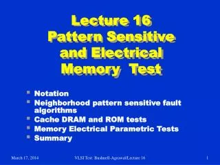
Lecture 15alt Memory NPSF and Parametric Test (Alternative for Lecture 16). Definitions of NPSFs NPSF test algorithms Parametric tests Summary References. Neighborhood Pattern Sensitive Faults. Definitions:

E N D
Lecture 15altMemory NPSF and Parametric Test(Alternative for Lecture 16) • Definitions of NPSFs • NPSF test algorithms • Parametric tests • Summary • References VLSI Test: Lecture 15alt
Neighborhood Pattern Sensitive Faults • Definitions: • Neighborhood – Immediate cluster of k cells whose operation makes a base cell fail • Base cell – A cell under test • Deleted neighborhood – A neighborhood without the base cell • ANPSF – Active NPSF • APNPSF – Active andPassive NPSF • PNPSF – Passive NPSF • SNPSF – Static NPSF • Assumption: Read operations are fault-free VLSI Test: Lecture 15alt
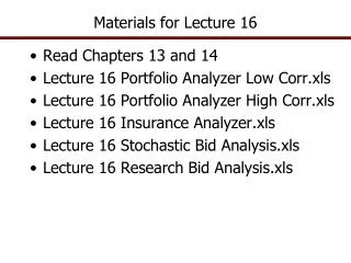
2 0 1 3 4 Type-1 Active NPSF • Active: Base cell changes when any one deleted neighborhood cell has a transition • Condition for detection and location: Each base cell must be read in state 0 and state 1, for all possible deleted neighborhood pattern changes. • Notation: C i,j< d0, d1, d3, d4 ; b > • Examples: • ANPSF: C i,j< 0, ↓ , 1, 1; 0 > • ANPSF: C i,j< 0, ↓ , 1, 1; ↕ > 2 – base cell 0, 1, 3 and 4 – deleted neighborhood cells k = 5 VLSI Test: Lecture 15alt
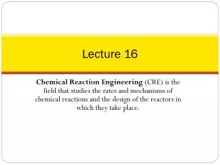
4 0 1 2 3 5 6 7 8 Type-2 Active NPSF • Used when diagonal couplings are significant 4 – base cell 0, 1, 2, 3, 5, 6, 7 and 8 – deleted neighborhood cells k = 9 VLSI Test: Lecture 15alt
Passive NPSF • Passive NPSF: A certain neighborhood pattern prevents the base cell from changing. • Condition for detection and location: Each base cell must be written and read in state 0 and in state 1, for all deleted neighborhood pattern changes. • ↑/ 0 ( ↓ / 1 ) – Base cell fault effect indicating that base cannot change VLSI Test: Lecture 15alt
Static NPSF • Static NPSF: Base cell forced into a particular state when deleted neighborhood contains particular pattern. • Differs from active – need not have a transition to sensitize an SNPSF • Condition for detection and location: Apply all 0 and 1 combinations to k-cell neighborhood, and verify that each base cell was written with a 1 and a 0. • Examples: • Ci,j < 0, 1, 0, 1; - / 0 > means that base cell forced to 0 • Ci,j < 0, 1, 0, 1; - / 1 > means that base cell forced to 1 VLSI Test: Lecture 15alt
NPSF Fault Detectionand Location Algorithm • write base-cells with 0; • loop apply a pattern; { it could change the base-cell from 0 to 1. } read base-cell; endloop; • write base-cells with 1; • loop apply a pattern; { it could change the base-cell from 1 to 0. } read base-cell; endloop; VLSI Test: Lecture 15alt
Number of NPSFs • Active Neighborhood Pattern Sensitive Faults (ANPSF) • Base cell 0 and 1 • ↑ and ↓ transitions in k – 1 cells • All 0-1 patterns in k – 2 cells • 2 (k – 1) 2 × 2k– 2 = (k – 1) 2k patterns • Passive Neighborhood Pattern Sensitive Faults (PNPSF) • Base cell ↑ and ↓ transition • All 0-1 patterns in k – 1 cells • 2 × 2k–1 = 2k patterns • Total APNPSF patterns = (k – 1) 2k + 2k = k 2k • Static Neighborhood Patterns (SNP) = 2k VLSI Test: Lecture 15alt
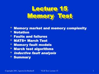
Sequencing Neighborhood Patterns with Minimal Writes End 100 110 k = 4 Start 000 010 101 111 Deleted neighborhood patterns 001 011 Hamiltonian path for SNPSF Eulerian path for ANPSF VLSI Test: Lecture 15alt
Hamiltonian Path, k = 5 1110 1111 1010 1011 0110 0111 1100 1101 end 0010 0011 1000 1001 0100 0101 0000 0001 start VLSI Test: Lecture 15alt
Hamiltonian Path, k = 5 1011 1111 1001 1101 0011 0111 1010 1110 0001 0101 1000 1100 0010 0110 0000 0100 VLSI Test: Lecture 15alt
2 2 2 2 2 2 2 2 2 2 0 0 0 0 0 0 0 0 0 0 1 1 1 1 1 1 1 1 1 1 3 3 3 3 3 3 3 3 3 3 4 4 4 4 4 4 4 4 4 4 0 0 0 0 0 0 0 Tiling for Type-1 Neighborhood 1 2 3 1 2 3 1 2 4 4 4 2 0 3 2 4 0 2 0 1 0 3 4 1 2 3 1 VLSI Test: Lecture 15alt
Total Patterns for n Cells k = neighborhood size = 5 or 9 VLSI Test: Lecture 15alt
NPSF Testing Algorithm Summary • A: active, P: passive, S: static • D: detection, L: location, 1/2: neighborhood, T: tiling, G: 2-group Fault Coverage Fault Loca- tion? No Yes Yes Yes Yes Yes Yes No Algorithm TDANPSF1G TLAPNPSF1G TLAPNPSF2T TLAPNPSF1T TLSNPSF1G TLSNPSF1T TLSNPSF2T TDSNPSF1G Oper- ation Count 163.5 n 195.5 n 5122 n 194 n 43.5 n 39.2 n 569.78 n 36.125 n SAF L L L L L L L L NPSF TF L L L A D L L L P L L L S L L L L D VLSI Test: Lecture 15alt
Fault Coverage Hierarchy APNPSF SNPSF ANPSF PNPSF TF SAF VLSI Test: Lecture 15alt
ROM Testing • Unidirectional SAF model -- only sa0 faults or only sa1 faults • Store cyclic redundancy code (CRC) on ROM, ATE reads ROM & recomputes CRC, compares with ROM CRC • Tests single-bit errors, double-bit errors, odd-bit errors, multiple adjacent errors VLSI Test: Lecture 15alt
Parametric (Electrical) Testing • Test for: • Major voltage / current / delay deviation from part data book value • Unacceptable operation limits • Divided bit-line voltage imbalance in RAM • RAM sleeping sickness – broken capacitor, leaks – shortens refresh interval VLSI Test: Lecture 15alt
DC Parametric Tests • Production test – done during burn-in • Applied to all chips • Chips experience high temperature + over-voltage power supply • Catches initial, early lifetime component failures – avoid selling chips that fail soon VLSI Test: Lecture 15alt
1. 2. 3. 4. 5. 6. 7. 1. 2. 3. Apply high to chip select, deselect chip Set chip pins to be in tri-state mode Force high on each data-out line – measure IOZ Force low on each data-out line – measure IOZ Select chip (low on chip select) Set read, force high on each address/data line, measure IL Set read, force low on each address/data line, measure IL Possible Test Outcomes: IOZ< 10 mA and IL< 10 mA (passes) IOZ≥10 mA (fails) IL≥10 mA (fails) Test Output Leakage Current VLSI Test: Lecture 15alt
1. 2. 3. 4. 1. Zero out memory. Increase supply above VCC in 0.01 V steps. For each voltage, read memory. Stop as soon as 1 is read anywhere, record voltage as Vhigh Fill memory with 1’s. Decrease supply below VCC in 0.01 V steps. For each voltage, read memory. Stop as soon as 0 is read anywhere, record voltage as Vlow. Possible Test Outcomes: Vhigh and Vlow inconsistent with data book (fails) Voltage Bump Test • Tests if power supply variations make RAM read out bad data VLSI Test: Lecture 15alt
AC Parametric Tests • Set a DC bias voltage level on pins • Apply AC voltages at some frequencies and measure terminal impedance or dynamic resistance • Determines chip delays caused by input and output capacitances • No information on functional data capabilities or DC parameters VLSI Test: Lecture 15alt
1. 2. 3. 4. 1. Split memory into two halves. Write 0’s in first half and 1’s in second half. Read entire memory and check correctness. Alternate between addresses in two halves Speed up read access time until reading fails, and take that time as access time delay. Access Time Tests • Characterization: • Use MATS++ with increasingly shorter access time until failure. • Use March C instead of MATS++. • Production test: run MATS++ at specified access time, and see if memory fails. VLSI Test: Lecture 15alt
Method: Perform read operations of 0s and 1s from alternating addresses at specified rapid speed. Alternate characterization method: Alternate read operations at increasingly rapid speeds until an operation fails. Running Time Tests VLSI Test: Lecture 15alt
Sense Amplifier Recovery Fault Tests • Write operation followed by read/write at different address Method: 1 Write repeating pattern dddddddd to memory locations (d is 0 or 1); 2 Read long string of 0s (1s) starting at first location up to location with d. 3 Read single 1 (0) from location with d. 4 Repeat Steps 2 and 3, but writing rather than reading in Step 2. VLSI Test: Lecture 15alt
Memory Test Summary • Multiple fault models are essential • Combination of tests is essential: • March – SRAM and DRAM • NPSF – DRAM • DC Parametric – Both • AC Parametric – Both • Related areas of memory test • BIST – standard practice for embedded memories • Repairable memories – redundancy to enhance yield VLSI Test: Lecture 15alt
References on Memory Test • R. D. Adams, High Performance Memory Testing, Boston: Springer, 2002. • M. L. Bushnell and V. D. Agrawal, Essentials of Electronic Testing for Digital, Memory and Mixed-Signal VLSI Circuits, Boston: Springer, 2000. • K. Chakraborty and P. Mazumder, Fault Tolerance and Reliability Techniques for High-Density Random-Access Memories, Upper Saddle River, New Jersey: Prentice Hall PTR, 2002. • K. Chakraborty and P. Mazumder, Testing and Testable Design of High-Density Random-Access Memories, Boston: Springer, 1996. • D. Gizopoulos, editor, Advances in Electronic Testing Challenges and Methodologies, Springer, 2006. • S. Hamdioui, Testing Static Random Access Memories: Defects, Fault Models and Test Patterns, Springer, 2004. • B. Prince, High Performance Memories, Revised Edition, Wiley, 1999. • A. K. Sharma, Semiconductor Memories: Testing Technology, and Reliability, Piscataway, New Jersey: IEEE Press, 1997. • A. J. van de Goor, Testing Semiconductor Memories, Chichester, UK: Wiley Interscience, 1991, reprinted by ComTex, Gouda, The Netherlands (http://ce.et.tudelft.nl/vdgoor/). VLSI Test: Lecture 15alt