Download
1 / 31
310 likes | 320 Views
Inductors and Magnetic fields. BITX20 bidirectional SSB transceiver. BITX20 bidirectional SSB transceiver. The Colpitts oscillator. See the BITX20 circuit LO: Local Oscillator BFO: Beat frequency Oscillator. Discharge of an Inductor. Graph of inductor discharge from 10A R=1 Ohm, L=1 Henry.

E N D
The Colpitts oscillator See the BITX20 circuit LO: Local Oscillator BFO: Beat frequency Oscillator
The same discharge from 27.18A e=2.718 10*2.718 10 10/2.718
Exponential decay The decay time constant = L / R If R is in Ohms and L in Henries the time is in seconds Every time constant the voltage decays by the ratio of 2.718 This keeps on happening (till its lost in the noise) This ratio 2.718is called “e”.
Exponential decay It’s a smooth curve. We can work out the current at any moment. The current at any time t is: I = I0 / e(t*R/L) I0 is the current at time zero. t*R/L is the fractional number of decay time constants For e( ) you can use the ex key on your calculator
Fields • Electric fields • Capacitors • Magnetic Fields • Inductors • Electromagnetic (EM) fields • Radio waves • Antennas • Cables
Construction of inductors www.germes-online.com
Key to diagrams Red rectangle = Outline of a Coil Blue Rectangle = Outline of a Core Red shading = Positive value Blue shading = Negative value Stronger shading is more positive / negative
Magnetic potential is measured in Amps! One often talks about Ampere turns but what counts is the total amps round a closed circuit. The magnetic potential between 2 points on an iron bar is equal to the current in a loop round the bar between those points
Magnetic field strength H is measured in Amps per metre Since magnetic potential is in amps the field strength H must be in amps per metre.
Magnetic flux density B is measured in Webers per square metre (Or Tesla)
Permeability • Magnetic field strength H (Amps/Metre) • Magnetic flux density B (Webers/m2) • B= μ * H (like Ohms law but for magnetics ) • Permeability μ = μ0 * μr • μ0 is 4 Pi*10-7 Henries per Metre (by definition of the Amp)
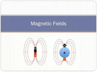
Induced Voltages • A moving magnet near a coil of wire will induce a voltage in the coil. This is due to the varying magnetic flux through the coil not the motion itself. • The voltage will be: • Voltage = Magnetic flux change per second times number of turns in the coil. • We can calculate the magnetic flux (in Webers)from the flux density B and the area.
Inductance When a current flows round a coil it produces a magnetic field. The magnetic field H produces a magnetic flux density B. Some or all of the flux (in Webbers) passes through the coil. If the current is varying then the magnetic flux varies. The varying magnetic flux causes a back EMF in the coil. We can calculate the inductance from the geometry and the permeability before making the coil.
Inductance of a toroid Toroids are the easiest to calculate since one can assume that their magnetic flux is uniform and only passes round the core. Magnetic field strength H = Amps * turns / circumference Magnetic flux density B = H * permeability Magnetic flux = B*cross section of toroid. Induced voltage = turns * Magnetic flux /second So induced voltage = (Amps /second)*turns*cross section* permeability* turns/circumference
Inductance of a toroid So for a Toroid (from previous slide): Induced voltage = (Amps /second)*turns*cross section* permeability* turns/circumference But for any Inductor: Induced voltage = (Amps/second)*Inductance So for any Toroid: Inductance = turns*turns*cross section* permeability /circumference
A real toroid example For a T37-2 toroid (all dimensions must be in metres) Mean circumference = 22.87*10-3 metres Cross section = 6.4*10-6 square metres Relative permeability = 10 So the permeability is = 12.57 * 10-6 So inductance = Turns squared * 3.51*10-9 Henries Or Turns squared * 3.51 nano Henries The manufacturers quote a value of: Turns squared * 4.3nH
What approximations did we make? A T37 toroid has an inner diameter of 5.21 mm and an outer of 9.35 mm Almost a 2:1 ratio. We assumed the flux was uniform across the cross section. In fact it will be almost double on the inner surface due to the higher magnetic field strength on the shorter path. We assumed the flux in the air was negligible. However this core has a relative permeability of only 10 so the flux in the air could be significant. (However by symmetry it should be small if the coil is wound evenly)