Download
1 / 7
70 likes | 82 Views
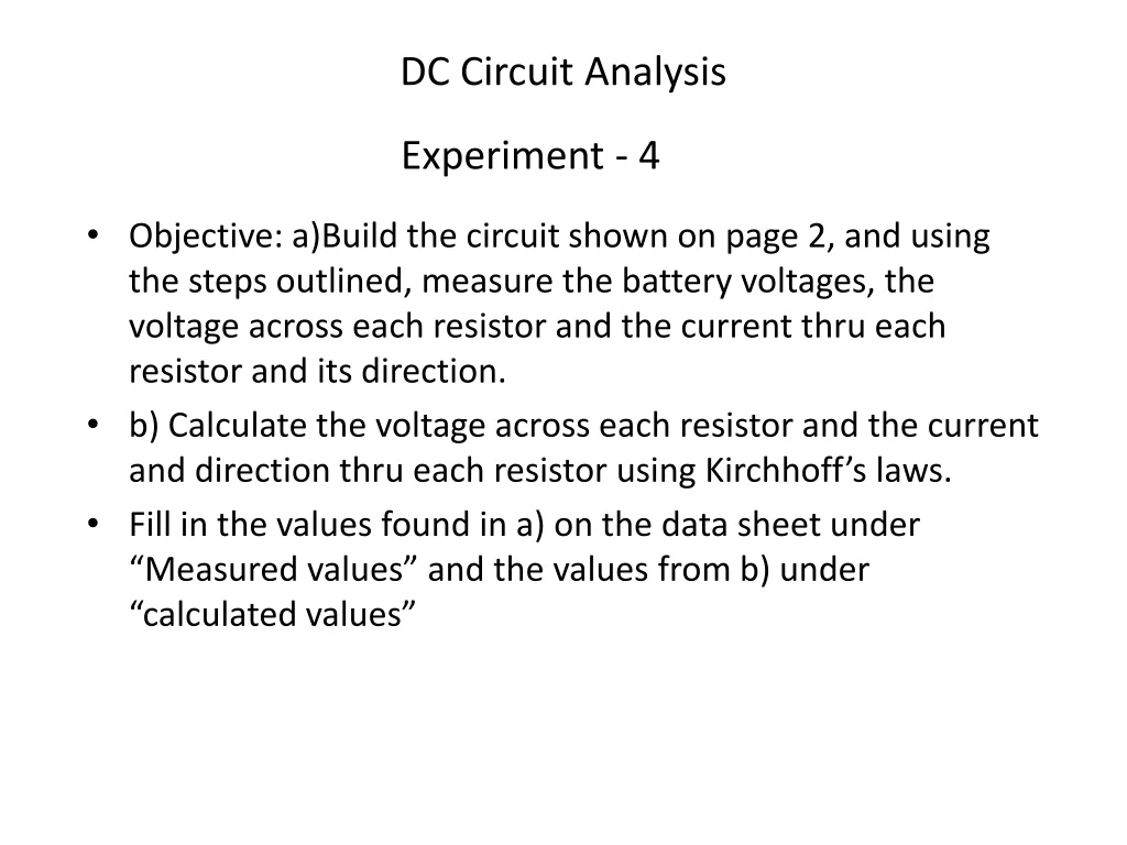
Experiment - 4. DC Circuit Analysis. Objective: a)Build the circuit shown on page 2, and using the steps outlined, measure the battery voltages, the voltage across each resistor and the current thru each resistor and its direction.

E N D
Experiment - 4 DC Circuit Analysis Objective: a)Build the circuit shown on page 2, and using the steps outlined, measure the battery voltages, the voltage across each resistor and the current thru each resistor and its direction. b) Calculate the voltage across each resistor and the current and direction thru each resistor using Kirchhoff’s laws. Fill in the values found in a) on the data sheet under “Measured values” and the values from b) under “calculated values”
Experiment - 4 Circuit Diagram R1 = 100Ω R2=200Ω DC Circuit Analysis V1=6v R3=300Ω V2=3v
Experiment - 4 Breadboard Layout DC Circuit Analysis R1 = 100Ω R2=200Ω V1=6v R3=300Ω V2=3v R2 - 200Ω R3 - 300Ω R1 - 100Ω
Experiment - 4 Layout and measurement instructions • Insert resistor R1 (100 ohms – Brown, Black, Brown) from d4 to Red Bus • Insert resistor R2 (200 ohms – Red, Black, Brown) from d14 to Red Bus • Insert resistor R3 (300 ohms blue resistor) from d9 to Red Bus • Connect Red clip lead from battery +6v terminal to R1 at d4 • Connect Black clip lead from battery – terminal to R2 at d14 • Connect 3rd clip lead from battery 3v terminal to R3 at d9 • Set DMM to 20vdc range • Measure voltages across resistors R1, R2, and R3 and enter on “measured values” data sheet . (Red lead to d4, Red Bus, Red Bus) • Switch DMM to the 20madc (current) range. • Disconnect Red lead from R1 at d4. • Connect the DMM Neg (Black) lead to R1 at d4 • Connect the DMM Pos (Red) lead to the battery +6v terminal. DC Circuit Analysis R1 = 100Ω R2=200Ω V1=6v R3=300Ω V2=3v 13. Read the current I1 and record on “ measured values” data sheet. 14. Disconnect the DMM leads and re-connect R1 per step 4 15. Disconnect the clip lead from R3 at d9 16. Connect the DMM Pos(Red) lead to R3 at d9 17. Connect the DMM Neg(Black) lead to the +3v battery terminal 18. Read the current I3 and record on data sheet.
Experiment - 4 Layout and measurement instructions 19. Remove DMM leads and re-connect R3 per step 6 20. Disconnect R2 from the Red Bus 21. Connect DMM Pos(Red) lead to R1 at Red Bus 22. Connect DMM Neg(Black) lead to R2 removed lead 23. Read current I2 and record on data sheet. Disconnect DMM leads and re-connect R2 lead per step 2 24. This completes the measured values. Be sure and include the polarity of all measured values on the data sheet. 25. Use the second data sheet to compute using Kirchhoffs laws the currents and voltages for each resistor. Fill in on data sheet 2 DC Circuit Analysis R1 = 100Ω R2=200Ω V1=6v R3=300Ω V2=3v
Experiment - 4 Data Sheet 1 – Measured Values A A A A VR2 = _____V VR1 = _____V R1 = 100Ω R2=200Ω + + DC Circuit Analysis I1 = _____ma I2 = _____ma + V1=6v VR3 = _____V R3=300Ω I3 = _____ma + + V2=3v Note: Draw your voltage loop arrows and current direction arrows on this sheet. = Ammeter locations (Three measurements)
DC Circuit Analysis Experiment - 4 Data Sheet 2 – Computed Values Compute the currents and voltages for each resistor. Enter here: VR1 = ________ v VR2 = ________ v VR3 = ________ v IR1 = ________ ma IR2 = ________ ma IR3 = ________ ma