Download
1 / 29
290 likes | 325 Views
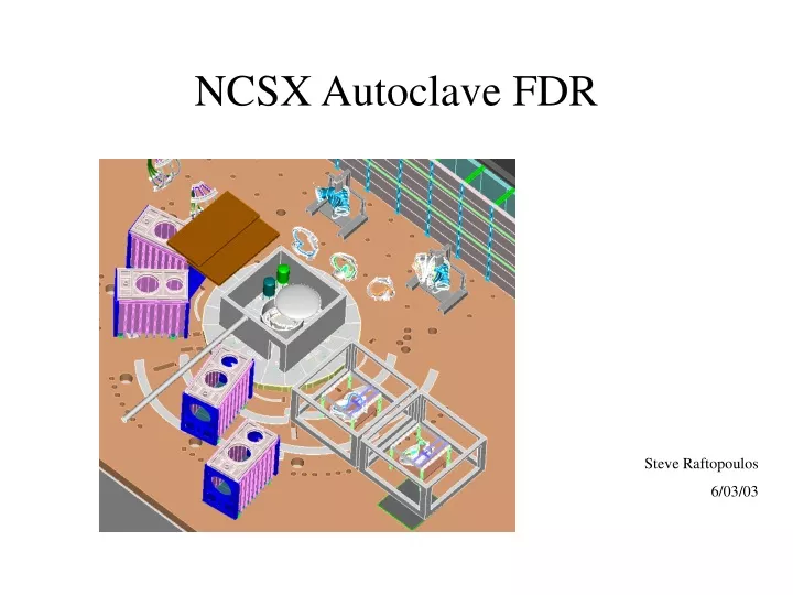
NCSX Autoclave FDR. Steve Raftopoulos 6/03/03. Agenda. Presentation: Intro & Background Requirements Design Analysis Results Review of PDR Chits Calculations Manufacturability Test requirements & Plans Costs Schedule Additional packages Drawings Specifications Calculations.

E N D
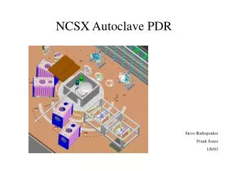
NCSX Autoclave FDR Steve Raftopoulos 6/03/03
Agenda • Presentation: • Intro & Background • Requirements • Design Analysis Results • Review of PDR Chits • Calculations • Manufacturability • Test requirements & Plans • Costs • Schedule • Additional packages • Drawings • Specifications • Calculations
Background The shape of the NCSX modular coil makes it impractical to build a rigid metal case, therefore a fiberglass case will be hand formed around the twisting geometry. For epoxy impregnation, typically a sealed case is built around the coil. Vacuum is pulled on the case, enabling the epoxy to flow into the winding and very effectively fill voids. Coil X-section
Background (cont.) Since this case is substantially weaker than a metal case, a vacuum will be pulled on both sides, minimizing the stress from differential pressure.
Major Design Requirements • Large enough to accommodate the NCSX modular coil sections (can also handle the TF Coils). • Can achieve and maintain a base vacuum of 1 torr in ~ four hours. • Can heat coil sections to 130 degrees centigrade. • Can accommodate a positive pressure of 15 psig. • Provide ports for: • Epoxy feedthroughs • Thermocouple feedthroughs • Viewports • Man entry • Three (3) Specifications have been generated – One “design-to” spec, and two “build-to” specs. They have been circulated for comments and are in the final sign-off process.
Design-tank • Dimensions - 5/8” thick, 14’ dia x 11” tall tube. • ASME dome heads (std catalog item). • 304SS vacuum chamber. • Support stand
Design (tank internal) LOWER DOME PLATFORM & VESSEL SUPPORT STRUCTURE • Floor at bottom of tank capable of supporting the modular coil (8 k#). • Platforms, external and internal to facilitate epoxy tanks, personnel ingress/egress, access to attachment of thermocouples and epoxy sprus. • Anchor points for cables to stabilize coil welded onto inside walls
Design (ports) • Two, 16.5-inch diameter ports for epoxy feedthroughs, each containing 19 sprus, will be available. One port just above midplane and one port at top of cylinder. • One, 16.5-inch diameter port that contains multiple, smaller (2.75”) thermocouple feedthroughs. • Two, 14-inch ports for the circulating heated air. Inlet port located in the lower dome, while the return port is located at the top of the cylinder. • One 10-inch diameter port that contains electrical feedthrough(s) for internal lighting. • Several spare ports available for “future considerations”. • One 32-inch man-way, with T-bolt, hinged closure. • Six 8-inch dia. round viewports for inspection, located to provide full viewing coverage of the sprue attachment points to coil.
Design (heating system) • Heating system consists of 72 kwatt (36-2kwatt electric resistive heaters), mounted to the outside surface of the tank. • Elements can be turned on in banks, allowing variable heating rates tailored to accommodate the modes of operation. • Additionally, 24 kwatt of heating shall be available in the form of circulating heated air. • Circulating air will improve heat transfer (convection oven effect). • Air is introduced at lower dome and is diffused by the perforated floor. 60-3/4” holes ensure that the flow is redistributed around the coil.
Design (Heating-Wall Heater Layout) -All heaters are mounted in pairs on exterior of tank (in 3 bands). The top and bottom bands are primary heaters consisting of 24-2000w strips. The center ring has 12- 2000w strips for secondary heat. -Fiberglass Insulation (min 1.5”) will retain heat and keep surface temperature to acceptable level (<100 degrees F)
Design(Heating-Circulating Heated Air System) • This system is “borrowed” from the NSTX TF coil bundle oven system. • Heaters: • 480 3Ø • require a minimum of 6 ft/sec @ 650ºF • Heater duct is 12”x24” • min flow required is 750 CFM • Blower: • Radial fan to provide high flow rates @ pressure • Max Temp is 600ºF • 208 3Ø • Insulation: • 1.5” min
Circulating Heated Air System Duct Pressure Loss and Velocity Pressure Results Job Number: Autoclave heating air Line Number: Oven Return 14” Round Fluid: Air Duct Type: ROUNDDuct Diameter (in): 14Flow Rate: 2200 SCFM Duct Length (ft): 30Viscosity (cP): 0.018Inlet Pressure (PSIG): 0Temperature (F): 260Duct Material: GALVANIZED METAL Duct Roughness (ft): 0.0005Fluid Velocity (ft/min): 2850.94Reynolds Number: 252886Flow Region: TurbulentFriction Factor: 0.018Density at Inlet: 0.055Specific Volume at Inlet: 18.122Specific Heat Ratio: 1.4 Straight Duct Loss (inches Water): 0.173Hood Entry Type: Flanged Duct End Hood Loss Factor: 0.49Hood Entry Loss (inches Water): 0.556Elbow Type 1: 4 piece Radius / Duct Diameter 1: 1.50Number Of Elbows 1: 3Elbow Sweep 1 (Degrees): 90Elbow Loss Factor 1: 0.27Elbow Loss 1 (inches Water): 0.302Duct Exit Configuration: Main Duct Line Exit Configuration Loss (inches Water): 0 Total Duct Loss (inches Water): 1.032 Velocity Pressure (inches Water): 0.373
Calculations • Calculations have been performed for the following: • Mechanical loads • Hoop stresses are very low. • buckling OK – checked with FEA by F. Dahlgren. • Thermal • Tank and components will require ~ 50 kW to heat in desired time frame. This considers heat loss from convection and conduction (very minor). The heating rate will be determined by the heat transfer from the hot air to the coil form. • 1.5 inch (min) of thermal insulation will be installed onto tank. This minimizes the heat loss and maintains the outer skin temperature below 100 F. • Vacuum • One 50cfm pump should be able to pump down the chamber to ~1 torr in 4-5 hours. Recommend that we have 2 pumps available. • The calculations have been checked.
Drawing Package • Drawing package is promoted to final design stage. • Any changes (as a result of this review) shall be incorporated and the package will be signed off and approved for fabrication.
ES&H concerns • The project is committed to the use of engineering and administrative controls to eliminate and/or minimize hazards to workers and the environments • Environmental • We’ll be pumping the off-gassing from the epoxy through the vacuum pumps and into the test cell. We will cold–trap these vapors. We’ve been doing this for the developmental work in the TCB since the fall of ’02. • Safety/IH • The autoclave chamber will be a confined space. Hazards include: • Oxygen deficiency • Electrical • Hot surfaces • Lifting/rigging • Elevated workspace • Vacuum hazards • These are hazards that have been successfully dealt with
Manufacturability (buy vs. build) • We plan to have the tank fabricated at PPPL. The major tank components (cylinder, domes, bolting flanges) will be procured from machining vendor(s), fabricated to our specifications per drawings. • We plan to purchase (or locate on-site) all other components that integrate into the system. • We see no major procurement issues at this time. All components are standard catalog items. Even tank domes are std. ASME design.
Testing Requirements & Plans • All acceptance requirements have been identified in the specifications. • Manufacturing: • Material specs • Weld inspections • Conformity to print • Operational: • Vacuum leak check • Pressure check (low pressure) • Heating system check • Vacuum pump check • ISTP: • Perform ISTP to test all systems. Could use the prototype modular coil form if it’s on-site. • Impregnation tests: • Impregnate the curved T-section test castings • Impregnate the prototype modular coil (if we have time)
Costs • Major M&S expenditures • Vacuum chamber $30,000 • Viewports $2000 • Man-way $1500 • TC feedthroughs free • Pumps free • Piping $2,000 • Valves $2,000 • Insulation $3,000 • Epoxy feedthrough ports free • Heating elements $6,000 • Structural steel $5,000 • Electrical M&S $15,000
Costs • Shop Labor estimates (mechanical & electrical) • Vacuum chamber machining 20 man-days SM • Ports (fab/weld/install) 20 man-days SM • Chamber legs/floor 15 man-days SM • Install heating elements 15 man-days TB • Chamber setup in TC 10 man-days TB • Vacuum piping fab 5 man-days SM • Vacuum system setup 5 man-days TB • Chamber setup in TC 10 man-days TB • Insulation 5 man-days TB • Platforms 10 man-days TB • Misc. Shop 15 man-days TB • Electrical Shop 40 man-days TB • Electrical Field 26 man-days TB • Totals • 60 M-days SM, 56 M-days in budget • 136 M-days TB, 100 M-days in budget
Schedule • Drafting/design Nov. 25 • Peer Review 12/9/02 • PDR 2/14/03 • RFQ Tank & lids June • Place tank/lids order July • Fab stand and ports June/July • Receive Tank/Lids Aug 15 • Mod Tank/Lids Aug/Sep • Ready for leak check Oct • Transfer to Test Cell Late Oct • Connect to services Nov • Shakedown/PTP Dec. • Ready to go Jan