Download
1 / 21
210 likes | 218 Views
TTC system and test synchronization. J. Varela Trigger Technical Coordinator ECAL Off-Detector Electronics Workshop, 7-8 April 2005, Lisbon. Outline. Reminder of TTC System ECAL specific issues Test system at Bldg 904. Trigger Fast Control. TTCmi. DAQ Event Managers. Global Trigger.

E N D
TTC system and test synchronization J. Varela Trigger Technical Coordinator ECAL Off-Detector Electronics Workshop, 7-8 April 2005, Lisbon
Outline Reminder of TTC System ECAL specific issues Test system at Bldg 904
Trigger Fast Control TTCmi DAQ Event Managers Global Trigger LHC-BST GPS aTTS Central Control Partition Control Partition Control Partition Control L1A Control Front-end Emulators, Trigger Rules Trigger Throttling System (sTTS and aTTS) Calibration and Test Triggers Dedicated runs, Special triggers during runs Synchronization Control Timing signals, Resync procedures Partitioning 8 independent partition groups, 8 independent triggers Local Triggers Local Control Local Control Local Control TTC sTTS TTC sTTS TTC sTTS FrontEnd FrontEnd FrontEnd TTCrx TTCrx TTCrx
Multi-Level Trigger Control Allows flexibility in commissioning/ debugging DAQ Event Manager TTCmi Global Trigger Control LHC-BST GPS aTTS TCS: CMS Control SubDetector Control LTC: SubDetector Control TTC TTS TTC TTS e.g. Magnet Test TTCci: Partition Control FrontEnd FrontEnd TTCrx TTCrx e.g. 904
Configurable Partitions Allows flexibility in commissioning/ debugging Trigger partitions match DAQ partitions
TTC System TTCcf – clock fanout CTC - central trigger control TIM - timing module BST - beam synchronous timing LTC - local trigger controller TTCci - CMS interface TTCex - encoder and transmitter TTCrx - receiver
Trigger Control Components GPS link To EVM GLOBAL TRIGGER CRATE To/from aTTS TTCmi Central Trigger Control ClockOrbit TTC (x 32) (x 32) TTS Fast Merging Module Local Triggers CPU int F M M TTCex TTCci F M M LTC TTS ... ... FMM TTC SYNC TTS TTS Link Subdetector Master TTC Crate TTC Link Local Trigger Controller From/To SUBDETECTOR CRATES
TTCci TTCci TTCci TTCci ECAL TTC Partitions VME -PCI VME 6U LTC FMM Partition 1 1 fiber Partition 2 1 fiber Partition 3 1 fiber Partition 4 1 fiber Optical coupler Optical coupler Optical coupler Optical coupler 9+1 fibers 18+1 fibers 18+1 fibers 9+1 fibers
8/17 0/9 Crate A1 far near far near Crate A EB EE(EE+) Crate A2 SM1 SM18 7/16 S1 S9 SM2 SM17 1/10 87.7 (85.3) SM3 SM16 85.7 (83.3) Crate C2 S2 S8 87.7 (85.3)) 83.7 (81.3) SM4 SM15 Max. 61.4 SM5 SM14 Max. length of fibers up to 1. rack edge row left bottom corner 85.2 (82.8) 81.7 (79.3) S3 S7 6/15 SM6 SM13 2/11 Crate C Crate B1 82.2 (79.8) 80.2 (77.8)) SM12 80.2 (77.8) SM7 S4 S6 SM8 SM11 S5 SM9 SM10 Crate C1 Crate B 3/12 5/14 Crate B2 4/13 Max.total length of fibers 81.3+6.4=87.7 87.7+4.6=92.3 85.2+7.6=92.8 85.3+4.0=89.3 83.7+5.2=88.9 82.8+7.0=89.8 wall to UX EE+ A 9-16-17 EE- A 0-7-8 EE- C 1-2-3 EE+ C 10-11-12 EE+ B 13-14-15 EE- B 4-5-6 SRP EB+ A1 9-17 EB+ A2 16-17 EB+ C2 10-11 EB+ C1 11-12 EB+ B1 14-15 TTCoc EB+ B2 13-14 Raw D EB- A1 0-8 EB- A2 7-8 EB- C2 1-2 EB- C1 2-3 EB- B1 5-6 EB- B2 4-5 0 9 1 10 2 11 3 12 4 E 17 8 16 7 15 6 14 5 13 2 3 4 5 6 7 8 9 1
2 prototypes exist Production of further 12 boards launched Software HAL-based device driver being written XDAQ overlay will also be implemented LTC LTC Local control of sub-detectors: - Up to 6 partitions- Input for 6 local triggers- Interface to 6 TTCci- Interface to one TTCvi (backward compatibility)- Interface to sTTS (6 channels)- Interface to aTTS (1 channel)- Interface to 4 Emulators -Interface to DAQ EVM (S-Link)- Interface to BST
1 prototype exists Production of further 15 boards launched TTCci TTCci L1A from CTC MUX L1A L1A from LTC To TTCex Channel-A Aux triggers Ch 1 B-Go from CTC Command code FIFO 5 ... MUX B-Go Decode B-Ch B-Go from LTC 5 Ch 16 Command code FIFO Clock, Orbit To TTCex Channel-B B-data Programmable
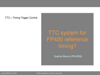
B-Go Channels Fast commands from CTC/LTC: Channel 4-bit code Command 1 0001 BC0 2 0010 Test Enable 3 0011 Private Gap 4 0100 Private Orbit 5 0101 ReSync 6 0110 HardReset 7 0111 Reset Event Counter 8 1000 Reset Orbit Counter 9 1001 Start 10 1010 Stop
3 1 0 7 6 5 2 4 TTC Broadcast Commands TTC 8-bit command code: BCR Coarse delay 2 ECR Coarse delay 1 CMS Rules: Assignment of B-channels (1 to 16) to CMS-wide Fast Controls is predefined Actual TTC broadcast command codes are stored in TTCci B-channels FIFOs Definition of these codes is done by the sub-detectors
ECAL TTC Broadcast Codes • Definition of ECAL TTC broadcast codes is now required. • Definition of codes for test triggers (laser, pedestal): • DCC readout may be a function of the trigger type • (e.g. LaserSM7a implies that only DCC of SM7/a is readout) • Other options are: zero suppression(?), SR flags (?) to select laser data
ECAL response to Resync To be cross-checked: DCC: - clear FIFOs and reset event counter SLB - toggle data/idle/data in the next GAP – resync trigger links to RCT TCC - clear FIFOs and reset event counter ? FE - clear FIFOs and reset event counter ? What is the response to HardReset? Clear FIFOs, reset EC, reset state machines (keep configuration registers)
Resync of Frontend Links • Links to DCC: • Between events, the links transmit Sync Patterns that are used to resynchronize the links • Links to TCC: • Are always transmitting data, no automatic resync possible • Local procedure controlled by software : • TCC identifies link out-of-sync and requests Sync Patterns to Supervisor • Supervisor requests Sync Patterns to FE (via CCS) • TCC identifies link in-sync and requests Data • TCC updates Condition DB
ECAL response to Calib Trigger • Calib Trigger = B-Go 2 (Test Enable) followed by L1A (fixed latency) • Send to whole CMS at a given frequency, during the Gaps • Central data acquisition, dedicated data stream in Filter Farm, available to Monitoring Farm • Usage in ECAL: • Laser triggers • Test Enable fires the Laser • Does the Laser control has a TTCrx as required? • Test sequence can be programmed in TTCci FIFO (SM sequence) • What is the latency between Test Enable and L1A required by ECAL?
ECAL private events • How to read laser events (in the LHC gap) into Local DAQ? • Use Private Gap (or Private Orbit) fast commands • Program TTCci to issue double TTC broadcasts: • TestEnable (to fire the laser) • LocalTrigger (B-command recognized by CCS-DCC-TCC as a trigger) CCS sends L1A to FE DCC and TTC handles local event (evt number, data to VME, block S-link) • Synchronization of EvNumber between FE and OD is a problem Possible solution DCC handles three event numbers: CMS event number Calib event number FE event number • Is there any advantage of using Local DAQ for laser events during running?
Test System @ Blg. 904 TTC Crate CAEN TTCvi ECAL OD Crate Tester Crate Trigger primitives CAEN STC TCC - T DCC-T TCC CCS D C C CAEN TTC signals, clock SR Flags FE Data Vitesse electrical links (SLB-STC) (from Nuno’s talk)
DCC Tester Board DCC-T is the source of Clock and TTC commands In present implementation there is no Slave Mode
Full Synchronized Test • Trigger Patterns loaded in TCC-T memories; Event Data loaded in DCC-T memories • TCC-T in Slave Mode: Clock and Start (w/ adjust. delay) from DCC-T • TCC-T cycles on Trigger Pattern memories • Frequency of periodic trigger is adjusted to capture always the same trigger data. • DCC-T provides Clock, BC0 and L1A to TTCci • TCC sends Primitives and SR flags to DCC at each L1A Requires new version of Tester Cards