Download
1 / 17
170 likes | 322 Views
DAQ for the TPC Sector Test at Test Beam T10. Klaus.Schossmaier@cern.ch ALICE DAQ Group ALICE TPC Collaboration Meeting Cagliari, Sardinia 16 – 17 May 2004. DAQ Requirements. Decision taken during ALICE week 15 – 19 March 2004 TPC Sector Test at PS Test Beam T10

E N D
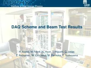
DAQ for the TPC Sector Testat Test Beam T10 Klaus.Schossmaier@cern.ch ALICE DAQ Group ALICE TPC Collaboration Meeting Cagliari, Sardinia 16 – 17 May 2004
DAQ Requirements • Decision taken during ALICE week 15 – 19 March 2004 • TPC Sector Test at PS Test Beam T10 • TPC prototype from Hall 167 • Complete IROC (~5000 channels) RCU readout via DDL • Si Beam telescope VME-based readout • Beam Time: 03 May (10 May) – 02 June 2004 • DAQ System • DATE software • 3.6 MB max. event size, 100 Hz max. trigger rate • ~1 TB data volume using CASTOR • RCU configuration via DDL • Integration with HLT • On-line/Off-line Monitoring TPC Collaboration meeting, 16-17 May 2004
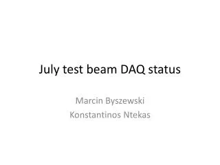
Detectors at Test Beam T10 IROC prototype of the TPC Sector 10 May 2004 Si Beam Telescope TPC Collaboration meeting, 16-17 May 2004
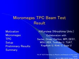
epaitbeam01 epaitbeam02 pcepess30 IROC Detector LDC HLT LDC Detector LDC DDL 1 Si BeamTelescope D-RORC 201 D-RORC 225DIU 262 VME processor CAEN VME boards DDL 2 D-RORC 202 RCU 1SIU 257 RCU 2SIU 251 DDL 3 DDL 4 10 MB/s Fast Ethernet DIU 248 DIU 250 1 MB/s HLT (3 PCs) HLT GDC CASTOR 1.5 TB SIU 247 3x 250 GB disk DDL 5 /castor/cern.ch/alice/testbeam2004/T10 epaitbeam03 DAQ Setup at T10 TPC Collaboration meeting, 16-17 May 2004
DDL (Detector Data Link) ~30 m IROC Detector LDC epaitbeam01 RCU 1 RCU 2 DDL 1 Integrated D-RORC incoming: DDL 2outgoing: DDL 4 to HLT Integrated D-RORC incoming: DDL 1outgoing: DDL 3 to HLT DDL 2 SIU attached to RCU 125 FECs (3200 ch.) SIU attached to RCU 218 FECs (2304 ch.) TPC Collaboration meeting, 16-17 May 2004
Farm PCs VME crate KVM epaitbeam01 2x Xeon 2.4GHzRH Linux 7.3.2 LDC: 2x D-RORC epaitbeam02 2x Xeon 2.4GHzRH Linux 7.3.2 LDC: 1x D-RORCServer epaitbeam03 2x Xeon 2.4GHz3x 250 GB diskRH Linux 7.3.4 GDC + CASTOR pcepess30 CCT VP CP1Pentium III 850MHzRH Linux 7.3.2 LDC: Si Telescope CAEN VMEbus Modules V262 – I/O registersV551B – CRAMS sequencer3x V50 – CRAMS(CAMAC) DAQ Linux Machines TPC Collaboration meeting, 16-17 May 2004
DATE v4.8 Software • Functions of LDC machines • Readout two integrated D-RORC in one LDC • Split data from the incoming DDLs to outgoing DDL for HLT • Readout one D-RORC with DIU from HLT via DDL • Configure the RCUs via the DDL with the FeC2 tool • Readout Si beam telescope (re-using Denis Nouais’ software) • Functions of GDC machines • Building full events from sub-events of the LDC machines DDL mini-header (8 32bit words) for event identification! • Recording to local disks or upload to CASTOR • On-line/Off-line monitoring • Functions of Server machines • RunControl, InfoLogger, DIM server, NFS, etc. TPC Collaboration meeting, 16-17 May 2004
DAQ Preparations • week 01-03-2004: planning of the DAQ started • week 08-03-2003: installation of an LDC in Lab 13-R-0025 for theintegration FEC RCU DDL FeC2 and DATE • week 15-03-2004: upgrading/fixing FeC2 • week 22-03-2004: moving LDCs to T10 • week 29-03-2004: moving VMEbus crate to T10; installation of DATE • week 05-04-2004: installation of the GDC with 3x 250GB disks • week 12-04-2004: testing DATE at T10; setting up MOOD • week 19-04-2004: installation of an LDC in Lab 13-R-0021 for the integration FEC RCU DDL HLT • week 26-04-2004: installation of the D-RORCs at T10; testing the data splitter with 2 LDCs for the HLT integration in Lab 4-R-0002 • week 03-05-2004: integration RCU DATE works (~80 MB/s) in Lab 13-R-0025; setting up CASTOR; cabling at T10; finishing and testing DDL setup; first data taking with 2x RCUs 2x DDLs DATE • week 10-05-2004: test runs without beam (e.g. pedestals) TPC Collaboration meeting, 16-17 May 2004
Running DATE TPC Collaboration meeting, 16-17 May 2004
Monitoring • Monitoring Modes: • On-line: sampling raw data from memory buffers • Off-line: sampling raw data from recorded files • Four Monitoring Tools: • eventDump: DATE low-level program hex dump • MOOD (Monitor Of On-line Data):- Toolkit for monitoring with interfaces for detector code- DATE Monitoring library to access raw data; ROOT environment - Visualization of beam position of Si Telescope developed by Ozgur Cobanoglu and Peter Christiansen; TPC data in progress • Roland Bramm’s Monitor:- re-used monitoring program for analyzing data from Hall 167- DATE Monitoring library to access raw data; ROOT environment- Visualization of TPC data • HLT Monitor: TPC Collaboration meeting, 16-17 May 2004
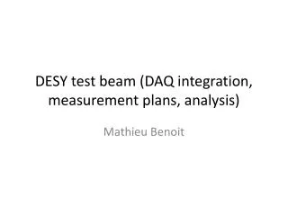
Monitoring with MOOD Beam position (raw data) of the Si Telescope Beam position (cluster finder) of the Si Telescope TPC Collaboration meeting, 16-17 May 2004
Monitoring TPC Data Roland’s Monitor: max. ADC of each channel attached to the 25 FECs connected to RCU 1 TPC Collaboration meeting, 16-17 May 2004
Field Experience • DDL Hardware • All connectors/cables/cards must be properly labeled • Choosing the right components (optical transceiver!) • End-to-end testing of each DDL link is necessary • DDL Software • Modifications of the FeC2 tool needed to increase the downloading speed (erroneous wait of acknowledge) • Additional FeC2 statements requested (e.g. WAIT) • Fixing low-level commands (prorc_receive, siu_reset) • DATE • Configuration is complex • Getting familiar with data format (DATE header structure) • DATE and FeC2 cannot run simultaneously on one LDC • A powerful and uniform Monitoring Tool is essential TPC Collaboration meeting, 16-17 May 2004
FeC2 Tool • FeC2 is a tool distributed with the DDL software of DATE to transmit commands and data blocks via the DDL to front-end cards (e.g. RCU, CarlosRX, Crocus). • FeC2 interprets a script of instructions: • Configure one RCU with 25 FECs (3200 channels): • 6400 data blocks (1kB and 2kB) • 9600 commands • Download speed for data blocks: • Current: Time [µs] = 0.2 · size [bytes] + 51 • Improved: Time [µs] = 0.01 · size [bytes] + 94 D-RORC with DIU # FeC2 script to configure a single channel write_block 0x0 block2kB.hex %xwrite_command 0x10Fwrite_block 0x0 block1kB.hex %xwrite_command 0x100write_command 0x10F DDL RCU with SIU TPC Collaboration meeting, 16-17 May 2004
Radiation Tolerant Tests Measurements on current SIU based on Altera ApexE • Cross section using protons (100 and 180 MeV): • Registers: σr = 1.33E-9 ± 0.15E-9 cm2 • Memory cells: σm = 1.46E-9 ± 0.11E-9 cm2 • Cross section using neutrons (14 MeV): • Registers: σr = 6.75E-11 ± 1.51E-11 cm2 • Memory cells: σm = 1.30E-10 ± 0.18E-10 cm2 • The SEU can introduce error during the transmission, but the error rate is negligible (< bit error rate). • The SEU can cause configuration loss, which will provoke ~1 error/hour at the level of the DAQ system! SIU Altera Apex EP20K60E (max. 162k system gates) TPC Collaboration meeting, 16-17 May 2004
Choosing FPGA for the SIU • Investigate new technology: Actel ProASIC+ • based on Flash technology which is more tolerant against radiation; capacity fits for the SIU (e.g. device APA150 has max. 150k system gates); concerns about speed • Same technology (SRAM) but with error detection and recovery: • Xilinx Virtex II: complete configuration read-back; partial reconfiguration during operation; triple module redundancy • Altera Cyclon and Stratix: built-in circuitry that monitors the configuration memory cells and detects errors • Next steps: • Combined test of the new devices in Uppsala (end of May 2004) • Choice of FPGA and final design of SIU board (Q3 2004 – Q2 2005) TPC Collaboration meeting, 16-17 May 2004
Conclusions • High participation of the ALICE DAQ team: • Material: PCs, DDL links, D-RORCs, cables, etc. • Manpower: meetings, hardware/software installation, customizations, testing, support • Several new DAQ components: • Hardware: integrated D-RORC, several 30 m DDL links • Software: two DDL links in one LDC, first integration with HLT, FeC2 under real conditions, on-line monitoring with MOOD • Plan of work: • Data taking with test beam • Integration with HLT • Maintenance of DDLs, DAQ machines, DATE • Moving back to Hall 167 ? http://test-alicetpc.webtest.cern.ch/test-alicetpc/ TPC Collaboration meeting, 16-17 May 2004