Download
1 / 40
400 likes | 647 Views
2.2 Microarchitecture 2.2b – Instruction Phases. Required : PM : Ch 8.1-3, pgs 109-114 Recommended : Wiki : Microarchitecture Wiki : Addressing_mode Wiki : Three-state logic. Learning Objectives…. After watching this video and studying the reading assignments, you should be able to:

E N D
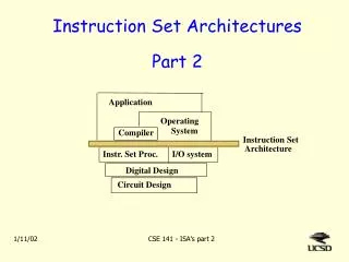
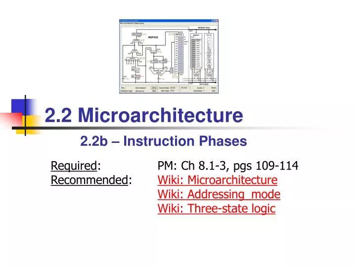
2.2 Microarchitecture2.2b – Instruction Phases Required: PM: Ch 8.1-3, pgs 109-114Recommended: Wiki: MicroarchitectureWiki: Addressing_modeWiki: Three-state logic
Learning Objectives… After watching this video and studying the reading assignments, you should be able to: • Describe computer instruction cycles. • Explain the purpose of the fetch cycle. • Understand the cycle relationship to addressing modes. • Explain the difference between PC-relative and absolute addressing modes. ISA
Instruction Cycle The Instruction Cycle • INSTRUCTION FETCH • Obtain the next instruction from memory • DECODE • Examine the instruction, and determine how to execute it • SOURCE OPERAND FETCH • Load source operand • DESTINATION OPERAND FETCH • Load destination operand • EXECUTE • Carry out the execution of the instruction • STORE RESULT • Store the result in the designated destination Not all instructions require all six phases MSP430 Microarchitecture
PC Fetch Cycle Fetching an Instruction PC can be incremented anytime during the Fetch phase MSP430 Microarchitecture
Addressing Modes The MSP430 has four basic addressing modes: 00 = Rs - Register 01 = x(Rs) - Indexed Register 10 = @Rs - Register Indirect (source only) 11 = @Rs+ - Indirect Auto-increment(source only) When used in combination with registers R0-R3, three additional source addressing modes are available: label - PC Relative, x(PC) &label – Absolute, x(SR) #n – Immediate, @PC+ (source only) Addressing Modes MSP430 Microarchitecture
Addressing Modes Addressing Mode Demo 8000: 540A 8002: 541A 0006 8006: 542A 8008: 543A 800a: 501A 0012 800e: 521A 801e 8012: 503A 0064 8016: 531A 8018: 1210 0004 801c: 3ff1 801e: 000a .text start: add.w r4,r10 ; r4 += r10; add.w 6(r4),r10 ; r10 += M[r4+6]; add.w @r4,r10 ; r10 += M[r4]; add.w @r4+,r10 ; r10 += M[r4++]; add.w cnt,r10 ; r10 += cnt; add.w &cnt,r10 ; r10 += cnt; add.w #100,r10 ; r10 += 100; add.w #1,r10 ; r10++; push cnt ; M[--r1] = cnt; jmp start cnt: .word 0x000a MSP430 Microarchitecture
00 = Register Mode Addressing Modes add.w r4,r10 ; r10 += r4 Address Bus Memory CPU Registers Data Bus (1 cycle) IR 0x540a +2 PC PC 0x540a ADDER PC R4 R10 ALU MSP430 Microarchitecture
Rs Evaluate Source Operand Source: Register Mode – Rs Select the source register MSP430 Microarchitecture
01 = Indexed Mode Addressing Modes add.w 6(r4),r10 ; r10 += M[r4+6] Address Bus Memory CPU Registers Data Bus (1 cycle) IR 0x541a +2 +2 PC PC PC 0x541a ADDER PC 0x0006 Data Bus (+1 cycle) R4 Address Bus R10 Data Bus (+1 cycle) ALU MSP430 Microarchitecture
Rs PC PC Evaluate Source Operand Source: Indexed Mode – x(Rs) PC incremented at end of phase Use PC to obtain index, use Rs for base register MSP430 Microarchitecture
10 = Indirect Register Mode Addressing Modes add.w @r4,r10 ; r10 = M[r4] Address Bus Memory CPU Registers Data Bus (1 cycle) IR 0x542a +2 PC PC 0x542a ADDER PC R4 Address Bus R10 Data Bus (+1 cycle) ALU MSP430 Microarchitecture
Rs Evaluate Source Operand Source: Indirect Mode – @Rs MSP430 Microarchitecture
Addressing Modes 11 = Indirect Auto-increment Mode add.w @r4+,r10 ; r10 += M[r4++] Address Bus Memory CPU Registers Data Bus (1 cycle) IR 0x543a +2 PC PC 0x543a ADDER PC 0002 Address Bus R4 R10 Data Bus (+1 cycle) ALU MSP430 Microarchitecture
Source: Indirect Auto Mode – @Rs+ Rs Evaluate Source Operand Increment by 1 (.b) or 2 (.w) MSP430 Microarchitecture
Addressing Modes 01 w/R0 = Symbolic Mode add.w cnt,r10 ; r10 += M[cnt] Address Bus Memory CPU Registers Data Bus (1 cycle) IR 0x501a +2 +2 PC PC PC PC 0x501a ADDER PC 0x000c Data Bus (+1 cycle) Address Bus cnt R10 Data Bus (+1 cycle) ALU *Also called PC Relative address mode MSP430 Microarchitecture
PC PC PC Evaluate Source Operand Source: Symbolic Mode – label PC incremented at end of phase Use PC to obtain relative index and for base register MSP430 Microarchitecture
Addressing Modes 01 w/R2 = Absolute Mode add.w &cnt,r10 ; r10 += M[cnt] Address Bus Memory CPU Registers Data Bus (1 cycle) IR 0x521a +2 +2 PC PC PC 0x521a ADDER PC 0xc018 Data Bus (+1 cycle) 0000 Address Bus cnt R10 Data Bus (+1 cycle) ALU MSP430 Microarchitecture
Source: Absolute Mode – &Address #0 PC Evaluate Source Operand PC can be incremented anytime during the phase Use PC to obtain absolute address, use #0 for base register MSP430 Microarchitecture
Addressing Modes 11 w/R0 = Immediate Mode add.w #100,r10 ; r10 += 0x0064 Address Bus Memory CPU Registers Data Bus (1 cycle) IR 0x503a +2 +2 PC PC PC 0x503a ADDER PC 0x0064 Data Bus (+1 cycle) R10 ALU MSP430 Microarchitecture
PC Evaluate Source Operand Source: Immediate Mode – #n PC can be incremented anytime during the phase MSP430 Microarchitecture
MSP430 Source Constants To improve code efficiency, the MSP430 "hardwires" six register/addressing mode combinations to commonly used source values: #0 - R3 in register mode (00) #1 - R3 in indexed mode (01) #2 - R3 in indirect mode (10) #-1 - R3 in indirect auto-increment mode (11) #4 - R2 in indirect mode (10) #8 - R2 in indirect auto-increment mode (11) Eliminates the need to use a memory location for the immediate value - commonly reduces code size by 30%. Evaluate Source Operand MSP430 Microarchitecture
Addressing Modes Constant Generator add.w #1,r10 ; r10 += 1 Address Bus Memory CPU Registers Data Bus (1 cycle) IR 0x531a +2 PC PC 0x531a ADDER PC 0000 0001 0002 0004 0008 ffff R10 ALU MSP430 Microarchitecture
Constant Mode – #{-1,0,1,2,4,8} R3 Evaluate Source Operand MSP430 Microarchitecture
Addressing Modes 3 Word Instruction add.wcnt,var ; M[var] += M[cnt] Address Bus Memory CPU Registers Data Bus (1 cycle) IR 0x5090 +2 +2 +2 PC PC PC PC 0x5090 ADDER PC PC 0x000c Data Bus (+1 cycle) 0x0218 Data Bus (+1 cycle) Address Bus cnt Data Bus (+1 cycle) Address Bus var ALU Data Bus (+1 cycle) Data Bus (+1 cycle) MSP430 Microarchitecture
Final Instruction Phases • Execute • PUSH • Decrement stack pointer (R1) • Ready address for store phase • JUMP • Compute 10-bit, 2’s complement, sign extended • Add to program counter (R0) • Store • Move data from ALU to register, memory, or I/O port MSP430 Microarchitecture
Execute Phase Push Instruction push.wcnt ; M[--sp] = M[cnt] Address Bus Memory CPU Registers Data Bus (1 cycle) IR 0x1210 +2 +2 PC SP PC SP PC PC 0x1210 ADDER PC fffe 0x000c SP Data Bus (+1 cycle) (+1 cycle) Address Bus cnt 0xa5a5 Data Bus (+1 cycle) Address Bus 0xa5a5 ALU Data Bus (+1 cycle) MSP430 Microarchitecture
Execute Phase: PUSH.W SP Use Store Phase to push on stack Execute Cycle SP = SP - 2 MSP430 Microarchitecture
Addressing Modes Execute Phase: jnefunc jnefunc ; pc += sext(IR[9:0]) << 1 Address Bus Memory CPU Registers Data Bus (1 cycle) IR 0x3c2a +2 PC PC 0x3c21 ADDER PC SEXT[9:0]<<1 R2 Jump Next COND func ALU MSP430 Microarchitecture
PC Execute Cycle Execute Phase: Jump Select “COND” to conditionally change PC 2’s complement, sign-extended MSP430 Microarchitecture
Store Cycle Store Phase: Rd MSP430 Microarchitecture
Store Cycle Store Phase: Other… MSP430 Microarchitecture
2.2.4 Review Questions • add.w tab(r10),r9 • and.w &mask,r12 • bis.b #0x08,r6 • mov.b cnt,r11 • mov.w r4,r5 • mov.w #100,r14 • sub.w @r4+,r5 • xor.b @r8,r15 • Absolute • Constant • Immediate • Indexed register • Indirect auto-increment • Indirect register • Register • Symbolic • Match the following source operand modes: MSP430 Microarchitecture
2.2.4 Review Questions (answers) • add.w tab(r10),r9 • and.w &mask,r12 • bis.b #0x08,r6 • mov.b cnt,r11 • mov.w r4,r5 • mov.w #100,r14 • sub.w @r4+,r5 • xor.b @r8,r15 • Absolute • Constant • Immediate • Indexed register • Indirect auto-increment • Indirect register • Register • Symbolic • Match the following source operand modes: MSP430 Microarchitecture
2.2.5 Review Questions Present the destination operand of the following instruction to the ALU: add.w r4,cnt ; M[cnt] += r4 Memory CPU PC PC PC PC ADDER Registers IR 0x5480 PC 0x5480 0x0218 R4 cnt ALU MSP430 Microarchitecture
2.2.5 Review Questions (answers) Present the destination operand of the following instruction to the ALU: add.w r4,cnt ; M[cnt] += r4 Memory Address Bus CPU +2 PC PC PC PC PC Put PC on Address Bus ADDER Registers PC IR 0x5480 2. Present ADDER Op1 w/Data Bus PC Data Bus (+1 cycle) 0x5480 0x0218 R4 3. Present ADDER OP2 w/PC 4. Put ADDER on Address Bus Address Bus 5. Load ALU OP2 from Data Bus Data Bus (+1 cycle) cnt ALU 6. Increment PC by 2 MSP430 Microarchitecture
2.2.6 Review Questions Show how to retrieve a PC-relative destination operand from memory and present to the ALU: MSP430 Microarchitecture
2.2.6 Review Questions (answers) PC PC PC Show how to retrieve a PC-relative destination operand from memory and present to the ALU: MSP430 Microarchitecture