Download
1 / 54
741 likes | 1.56k Views
CHAPTER 4 MACROMECHANICAL ANALYSIS OF LAMINATES. Dr. Ahmet Erkliğ. Laminate Code. A laminate is made of a group of single layers bonded to each other. Each layer can be identified by its location in the laminate, its material, and its angle of orientation with a reference axis.

E N D
CHAPTER 4MACROMECHANICAL ANALYSIS OF LAMINATES Dr. Ahmet Erkliğ
LaminateCode A laminate is made of a group of single layers bonded to each other. Eachlayer can be identified by its location in the laminate, its material, and itsangle of orientation with a reference axis.
LaminateCode [0/–45/90/60/30] or [0/–45/90/60/30]T [0/-45/902/60/0] subscript s outside the brackets represents that the three plies are repeated in the reverse order. T stands for a total laminate.
Special Types of Laminates • Symmetric laminate: for every ply above the laminate midplane, there is an identical ply (material and orientation) an equal distance below the midplane • Balanced laminate: for every ply at a +θ orientation, there isanother ply at the – θ orientation somewhere in the laminate • Cross-ply laminate: composed of plies of either 0˚ or 90˚ (no other ply orientation) • Quansi-isotropic laminate: produced using at least three different ply orientations, all with equal angles between them. Exhibits isotropic extensional stiffness properties
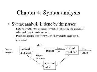
Strain-DisplacementEquations The classical lamination theory is used to develop these relationships.Assumptions: • Each lamina is orthotropic. • Each lamina is homogeneous. • A line straight and perpendicular to the middle surface remainsstraight and perpendicular to the middle surface during deformation
Strain-Displacement Equations • The laminate is thin and is loaded only in its plane (plane stress) • Displacements are continuous and small throughout the laminate • Each lamina is elastic • No slip occurs between the lamina interfaces
Strain-Displacement Equations Nx = normal force resultant in the x direction (per unit length) Ny = normal force resultant in the y direction (per unit length) Nxy = shear force resultant (per unit length)
Strain-Displacement Equations Mx = bending moment resultant in the yz plane (per unit length) My = bending moment resultant in the xz plane (per unit length) Mxy = twisting moment resultant (per unit length)
Strain-Displacement Equations Curvatures in the laminate Distance from the midplane in the thickness direction Midplane strains in the laminate
Coordinate Locations of Plies in a Laminate Consider a laminate made of n plies. Each ply has athickness of tk. Then the thickness of the laminate h is
Coordinate Locations of Plies in a Laminate The z-coordinate of each ply k surface (top and bottom) isgiven by Ply 1: Ply k: (k = 2, 3,…n – 2, n – 1): Ply n:
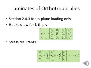
Integrating the global stresses in each lamina gives the resultant forces perunit length in the x–y plane through the laminate thickness as Similarly, integrating the global stresses in each lamina gives the resulting moments per unit length in the x–y plane through the laminate thickness as
The midplane strains and platecurvatures are independent of the z-coordinate. Also, the transformedreduced stiffness matrixis constant for each ply.
Force and Moment Resultant [A] – extensional stiffness matrix relating the resultant in-plane forces to the in-plane strains. [B] – coupling stiffness matrix coupling the force and moment terms to the midplane strains and midplane curvatures. [D] – bending stiffness matrix relating the resultant bending moments to the plate curvatures.
Analysis Procedures for Laminated Composites • Find the value of the reduced stiffness matrix [Q] for each ply usingits four elastic moduli, E1 , E2 , ν12 , and G12 • Find the value of the transformed reduced stiffness matrix [] for each ply using the [Q] matrix calculated in step 1 and the angle ofthe ply • Knowing the thickness, tk , of each ply, find the coordinate of the topand bottom surface, hi , i = 1…, n, of each ply. • Use the [] matrices from step 2 and the location of each ply fromstep 3 to find the three stiffness matrices [A], [B], and [D]
Analysis Procedures for Laminated Composites • Substitute the stiffness matrix values found in step 4 and the appliedforces and moments • Solve the six simultaneous equations to find the midplanestrains and curvatures. • Now that the location of each ply is known, find the global strainsin each ply • For finding the global stresses, use the stress–strain • For finding the local strains, use the transformation • For finding the local stresses, use the transformation
Example Find the three stiffness matrices [A], [B], and [D] for a three-ply [0/30/-45]graphite/epoxy laminate as shown in Figure. Assume that each lamina hasa thickness of 5 mm.
Solution Step 1: Find the reduced stiffness matrix [Q] for each ply
Step 2: Find the transformed stiffness matrix [] using the reduced stiffness matrix [Q] and the angle of the ply
Step 3: Find the coordinate of the top and bottom surface of each plyusingequation 4.20 The total thickness of the laminate is h = (0.005)(3) = 0.015 m. The midplane is 0.0075 m from the top and the bottom of the laminate. Ply n: h0 = –0.0075 m h1 = –0.0025 m h2 = 0.0025 m h3 = 0.0075 m
Example 2 A [0/30/–45] graphite/epoxy laminate is subjected to a load of Nx = Ny =1000 N/m.Find, • Midplane strains and curvatures • Global and local stresses on top surface of 30° ply
The strains and stresses at the top surface of the 30° ply are foundas follows. First, the top surface of the 30° ply is located at z = h1 =–0.0025 m.