Download
1 / 28
300 likes | 497 Views
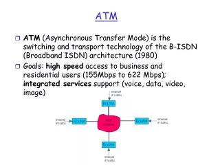
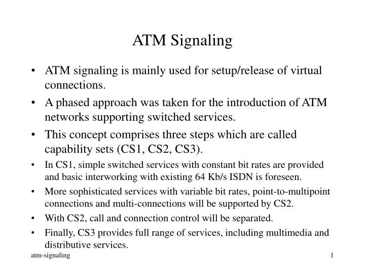
ATM Signaling. ATM signaling is mainly used for setup/release of virtual connections. A phased approach was taken for the introduction of ATM networks supporting switched services. This concept comprises three steps which are called capability sets (CS1, CS2, CS3).

E N D
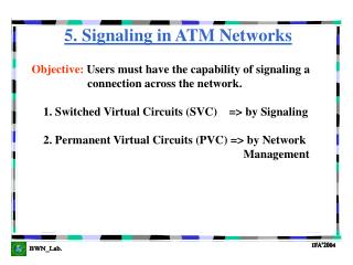
ATM Signaling • ATM signaling is mainly used for setup/release of virtual connections. • A phased approach was taken for the introduction of ATM networks supporting switched services. • This concept comprises three steps which are called capability sets (CS1, CS2, CS3). • In CS1, simple switched services with constant bit rates are provided and basic interworking with existing 64 Kb/s ISDN is foreseen. • More sophisticated services with variable bit rates, point-to-multipoint connections and multi-connections will be supported by CS2. • With CS2, call and connection control will be separated. • Finally, CS3 provides full range of services, including multimedia and distributive services.
ATM Forum UNI Signaling • ATM Forum UNI signaling specifications are based on the specifications of ITU-T. • ATM Forum UNI 3.0 • ATM Forum UNI 3.1 • ATM Forum UNI 4.0 • UNI 4.0 provides features such as - anycast: A user of a specific service need not know which entity in the network actually performs the service, and instead can use a published group address assigned to this service. The network can automatically distribute service requests to the service-providing group members. - leaf-initiated join: join an already established VCC. - proxy-signaling: a user performs signaling for one or more other users.
Q.2931 Q.2931 S-AAL S-AAL MS ATM ATM PHY PHY Protocol Architecture for CS1 - Point-to-point: Only one signaling endpoint on the user side. A single permanently established point-to-point SVC is required. - Point-to-Multipoint: Several signaling endpoints are located at the user side. Meta-signaling is necessary to manage other signaling relations. • Two signaling access configurations at the UNI: Point-to-point signaling access Point-to-multipoint signaling access
Protocol Architecture for CS1 • At the NNI, either the existing STM-based common channel signaling system no. 7 (SS7) or an ATM based network can be used to transport the signaling messages. B-ISUP B-ISUP MTP-3 MTP-3 S-AAL MTP-2 ATM MTP-1 PHY STM based signaling network ATM-based signaling network
SSCF SSCOP CP convergence sublayer SAR ATM Adaptation Layer for Signaling • A suitable signaling AAL (S-AAL) is required in order to adapt the signaling application protocols to the services provided by the underlying ATM layer. • ITU-T uses AAL5 for Common part. Service-Specific Part Common Part
S-AAL Service Specific Part • The service-specific connection-oriented protocol (SSCOP) provides mechanisms for the establishment and release of connections and the reliable exchange of signaling information between signaling entities. • The service-specific coordination functions (SSCFs) map the requirements of the layer above to the requirements of the next lower layer. • ITU-T uses a common SSCOP for UNI and NNI. • SSCOP could have been designed by using an existing data link layer protocol, with some modifications. • ITU-T decided to specify a new protocol for SSCOP. • ITU-T uses AAL5 for Common part.
SSCOP Functions • Sequence Integrity: preserve SDU order • Error correction by retransmission: error detected by sequencing mechanism; corrected by selective retransmission. • Flow control: receiver controlled; by dynamic window mechanism. • Error reporting to layer management: • Keep alive: • Local data retrieval: SDUs can be retrieved which have not yet been delivered • Link management: establish/release SSCOP connections • Transfer of Data: assured or unassured • PCI error detection: errors within PCI are detected • Status reporting • ITU-T uses AAL5 for Common part.
Signaling Protocols for CS1 - UNI: Q.931, layer 3 protocol for 64 Kb/s ISDN - NNI: ISDN User Part (ISUP) • Reuse of existing protocols with some modifications. • Q.2931 is the layer 3 signaling protocol for B-ISDN. - Q.2931 includes the specification of the signaling messages, information elements and communication procedures between signaling endpoints for the B-ISDN UNI. - Main modifications from Q.931: - a new information element (IE) for users to select between different AAL classes and the associated protocols. - a new connection identifier IE consisting of VPCI and VCI. (The Virtual Path Connection Identifier identifies a VPC while a VPI identifies a VP link. VPCI is necessary because a VP cross-connect may exist between the local exchange and the TE.)
Signaling Messages - Call Proceeding - Connect - Connect Acknowledge - Setup • Call establishment messages • Call clear messages • Status Messages • Global Call Reference Related Messages • Point-to-Multipoint Connection Control - Release - Release Complete - Status Enquiry - Status (Response) - Add Party - Add Party Acknowledge - Add Party Reject - Drop Party - Drop Party Acknowledge
UNI UNI Destination Source Network SETUP SETUP CALL PROCEEDING CALL PROCEEDING CONNECT CONNECT CONNECT ACK CONNECT ACK RELEASE RELEASE RELEASE COMPLETE RELEASE COMPLETE UNI Point-to-Point Signaling Example
Signaling Message • Each message contains several common mandatory information elements: protocol discriminator (1) call reference (4) • message type (2) • message length (2) • variable length info • elements, as required (1)
ATM Addressing • ATM uses two basic types of addresses: E.164 and AESA (ATM end system addresses). • Telecom uses the global ISDN numbering plan specified in ITU-T E.164. • AESAs are based on ISO NSAP (network service access point). • Computer networks mostly employ the OSI NSAP addressing mechanism. • E.164 addresses comprise 15 digits (8 bytes): country code + area or city code + subscriber number. • ATM Forum chose 20-octet NSAP address format and encoding for addressing of ATM systems connected to a private network; systems connected to an public network can use either NSAP or E.164 addresses.
ATM Addressing • Current version of the NSAP addressing planes • Three addressing formats • DCC (Data Country Code): the country with an address is registered • ICD (International Code Designator): an international organization • E.164: ISDN & telephone numbers • Each address is composed of IDP (Initial Domain Part) & DSP (Domain Specific Part). • AFI (Authority and Format Identifier): Which of the formats • IDI (Initial Domain Identifier): specifies the Authority that allocates the DSP that follows.
(a) DCC ATM format 1 3 13 19 20 AFI DCC HO-DSP ESI SEL IDP DSP IDI (b) ICD ATM format 1 3 13 19 20 AFI ICD HO-DSP ESI SEL IDP DSP IDI (c) E.164 ATM format 1 9 13 19 20 AFI E.164 HO-DSP ESI SEL IDP DSP IDI
The number is coded in Binary Coded Decimal (BCD) • PAD: with zeroes on the left side • 15 digits constant length
Network A Network B PNNI PNNI PNNI • The private network-network interface (PNNI) is a trunking, routing and signaling protocol specified by the ATM Forum. It is an inter-switch protocol which supports SVC between switches of multiple vendors.
Source Switch Transit Switch Destination Switch Source A Destination B SETUP SETUP SETUP SETUP CALL PROCEEDING CALL PROCEEDING CALL PROCEEDING CALL PROCEEDING CONNECT CONNECT CONNECT CONNECT CONNECT ACK CONNECT ACK CONNECT ACK CONNECT ACK RELEASE RELEASE RELEASE RELEASE COMPLETE RELEASE RELEASE COMPLETE RELEASE COMPLETE RELEASE COMPLETE PNNI Signaling Example
Logical Link A B Logical Group Node Peer Group Leader PG(A) A.2 A.1 PG(B) PG(A.2) PG(A.1) B.1 A.2.2 A.1.2 B.3 A.2.3 A.2.1 A.2.4 B.2 A.1.3 A.1.1 B.4 Physical Link Example of PNNI Hierarchy
A.2 B A.1.2 A.1.3 A.1.1 Topology seen by Switch A.1.1 DTL: Designated Transit List DTL: [A.1.1, A.1.2] DTL: [A.1, A.2] DTL: [A, B]
A.2 B A.1.2 A.1.3 A.1.1 Switch A.1.2 When A.1.2 receives the call setup message, it finds that it is at the end of top DTL, so it removes the top DTL and sends The message to A.2 (via A.2.1). DTL: [A.1.1, A.1.2] DTL: [A.1, A.2] DTL: [A, B]
Switch A.2.1 When A.2.1 receives the call setup message, it finds that A.2 has been reached. So it builds a route to B (say via A.2.3 and A.2.4) and pushes a new DTL onto the stack. DTL: [A.2.1, A.2.3, A.2.4] DTL: [A.1, A.2] DTL: [A, B] A.2.2 A.1 B A.2.4 A.2.1 A.2.3
Switch A.2.4 When A.2.4 receives the call setup message, it finds that the targets at the top two DTLs have been reached. So it removes the top two DTLs and forwards the message with the following DTL to its neighbor: DTL: [A.2.1, A.2.3, A.2.4] DTL: [A.1, A.2] DTL: [A, B] A.2.2 A.1 B A.2.4 A.2.1 A.2.3
Switch B.1 When B.1 receives the call setup message, it finds that the current DTL has been reached. B.1 builds a new DTL, resulting in DTL: [B.1, B.3] DTL: [A, B] B.1 A B.3 B.2 B.4
Switch B.3 When B.3 receives the call setup message, it finds that it is the DTL terminator since all DTLs are at the end. DTL: [B.1, B.3] DTL: [A, B] B.1 A B.3 B.2 B.4