Download

1 / 23
250 likes | 394 Views
Testing of Advanced Conformal Ablative TPS. Matthew Gasch NASA Ames Research Center, Moffett Field, CA, 94035 Parul Agrawal ERC at NASA Ames Research Center, Moffett Field, CA, 94035 Robin Beck NASA Ames Research Center, Moffett Field, CA, 94035.

E N D
Testing of Advanced Conformal Ablative TPS Matthew Gasch NASA Ames Research Center, Moffett Field, CA, 94035 Parul AgrawalERC at NASA Ames Research Center, Moffett Field, CA, 94035 Robin Beck NASA Ames Research Center, Moffett Field, CA, 94035 International Planetary Probe Workshop-10, June 17-21, 2013
Outline • Technology Description • SPRITE Test Design and Results • Summary
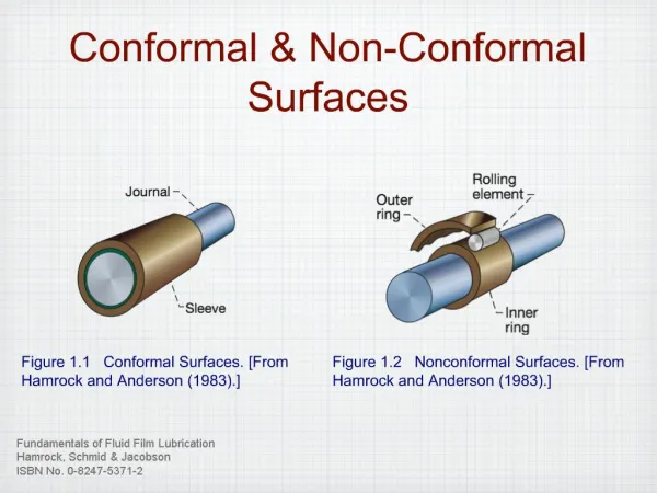
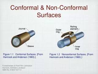
Technology description: Conformal TPS • Reinforcement on low density carbon or polymer felts • High strain to failure eliminates need for strain isolation during attachment to rigid aeroshell (required for PICA) • Allows for large area ablators • Eliminates gaps and gap filler issues present with standard PICA • Impregnation with advanced polymer resins to improve properties • Reduce thermal conductivity • Endothermic energy absorption due to decomposition of the resin • Increased char strength Carbon Felt After Impregnation
SPRITE 250 Project - Conformal TPS Goal • Conformal TPS Materials Development to TRL 5 • Develop and demonstrate (via ground testing) a conformal ablator capable at 250 W/cm2 and beyond • Based on felt reinforcements that come in very large sizes • Reduced part counts (compared to PICA) • High strain-to-failure eliminates/reduces gap and gap filler issues common with PICA • Our assumptions are: • Commercially available felt systems such as carbon felt, and simpler steps in making conformal TPS will lower the cost • Conformal is going to be less complex to integrate across a variety of carrier structure – lower design complexity • Conformal is going to be cheaper to manufacture and install
Test Campaigns • Test 1: 2012 Arcjet test series • Assess the thermal performance of proposed materials over a broad range of conditions • Develop TPS-C instrumentation for developing and validating thermal response models from TPS materials testing in the arcjet • Down-select one conformal material for further testing. • Test 2: 2013 Arcjet test series • Develop mid-fidelity material response models that can predict recession and in-depth temp response in support of mission design and analysis • Address attachment of conformal TPS to a rigid carrier structure and seam design between gore panels
SPRITE Configuration SPRITE1 – Small Probe Reentry Investigation for TPS Engineering Advantages Enables the testing in relevant environment It is possible to obtain a flight like pressure, shear and heatflux distribution Can test standard TPS against conformal material within the same model resulting in cost savings. Enables testing of seams in relevant test conditions a) Wood model in arcjet. b) Flow simulations for pressure distribution.2 1Empey, D. M., Sergey Gorbunov, Skokova, K.A., Agrawal P., Swanson G., Prabhu, D.K., Peterson K. H., and Venkatapathy E., “Small Probe Reentry Investigation for TPS Engineering (SPRITE)”, AIAA 2012-0215. 2 Prabhu, D. K., “FlowfieldAnalysis of a Small Entry Probe (SPRITE) Tested in an Arc Jet”, AIAA 2012-0216.
SPRITE Test Article Detail ConformalTPS PICA Nose • 8-inch diameter • 550 sphere cone
MSL Peak Aerothermal Environment 250 W/cm2, 0.33 Atm, 490 Pa Shear
CFD Analysis: High Condition High Condition “MSL” ~ 400 W/cm2, ~ 24 kPa Press. ~ 200 Pa shear on Flank and ~ 500 Pa shear On 0.8”Rb corner CFD by Dinesh Prabhu
CFD Analysis: Medium Condition Medium Condition “MSL” ~ 180 W/cm2, ~ 13 kPa Press. ~ 150 Pa shear on Flank and ~ 300 Pa shear On 0.8”Rb corner CFD by Dinesh Prabhu
Test 1: Test Matrix and Instrumentation • 4 inch hemi calorimeters to characterize the flow • Each model was instrumented with 4 TC- plugs with 3 TCs in each plug. The data from all the 12 TCs was collected during the test. • Infrared camera and pyrometer were mounted to obtain surface temperature. • Laser scans were obtained pre- and post- arcjet to measure recession.
Test 1- Thermocouple Data • The conformal TC plugs worked well and we were able to obtain reasonable measurements from these test to develop thermal response model. Top TC Top TC C-PICA C-SICA Bondline TC Bondline TC
Test 1- Recession Summary Table C-PICA model in high condition
Test 1 – Conclusions • The tests proved that conformal ablator technology is a viable option. • C-PICA was down-selected to be advanced to a higher TRL based on ease of processing , machining. • The next step was to test gaps and seams for conformal ablator. Post test C-PICA Post test C-SICA
Test 2: Pre-Test Images Seam Model PICA PICA PICA Thermal Response Model
Test 2: Test Matrix and Instrumentation • Test Details: • Articles tested at 4 conditions: 40, 130, 180 & 400 W/cm2 • 4-inch hemispherical calorimeters were used to characterize the flow • 4 TC plugs (0.15, 0.30 & 0.50-inch depth) – 1 in each TPS segment • IR and Pyrometer data were obtained for surface temperature • Pre and post- arcjet laser scans were obtained.
Test 2: Video of Seam Model Testing at high (~400 W/cm2) condition
Test 2: Models During and After Exposure Thermal Response Model Seam Model
Test 2: Post test laser scan • Recession comparable to PICA SEAM -1 (high condition) TR -1 (high condition)
Bondline Temperature: ~40 W/cm2, 100 sec • The thermocouple data consistently showed significantly lower bondline temperature for conformal PICA. Standard PICA Conformal PICA
SPRITE Test Summary • Objectives of the test were met: • Demonstrated applicability of conformable ablator on a curved structure at range of conditions from 40-400W/cm2 • MSL-heat flux and COTS LEO shear conditions • Demonstrated advanced instrumentation of conformable ablators and gathered in-situ temperature data • Gathered recession and back-face temperature data on conformable ablators in a representative shear environment • Evaluated 5 seam designs. All the seams performed very well in the arcjet environments. No widening of gaps, redeposit etc were observed during the test. The two tests proved that Conformal PICA is a viable technology solution that addresses the issues of gap fillers and seams with standard PICA , while proving a lower bondline temperature.