Download
1 / 41
410 likes | 512 Views
Jussi Nieminen Last update 11.1.2010. UDP2HIBI usage+implementation. Purpose. Connect FPGA board to PC Use cross-connected ethernet cable Structure Controller for Ethernet PHY chip Block for handling UDP headers Adapter to interface with HIBI (main focus of this document).

E N D
Jussi Nieminen Last update 11.1.2010 UDP2HIBI usage+implementation
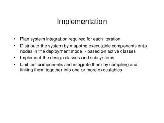
Purpose • Connect FPGA board to PC • Usecross-connectedethernetcable • Structure • Controller for EthernetPHY chip • Block for handling UDP headers • Adapter to interfacewithHIBI (main focus of this document)
Use case example • Transferring data between a PC and an SDRAM • Nios controls the events but the transfer itself happens between the SDRAM and the PC • In the name of simplicity, some less relevant blocks have been left out from the following diagrams Ethernet controller NIOS II UDP/IP NIOS2HIBI UDP2HIBI HIBI HIBI SDRAM controller SDRAM
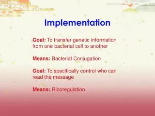
HIBI UDP Basics • Interfacebetween a UDP/IP block and the HIBI bus • Capable of handlingone transmission and oneincomingpacket at a time • UDP2HIBI uses HIBI addresses to separatetransfersfromdifferentagents • Soallagentsmustusedifferentaddresseswhensending to UDP2HIBI
Tx side • Before a transfer can begin, the UDP2HIBI must be configured by sending a configuration packet • Sets destination IP address and UDP ports • Locks the UDP2HIBI to the used hibi address so that no one else can interfere with the transfer. • The transfer is started with a specific tx header • Sets the tx length • After the header, all words sent by that agent are considered as data until tx length of bytes has been received • After the transmission the UDP2HIBI must be released with a release packet so that others can use it
Sequencediagram CPU 2 UDP2HIBI CPU 1 Tx configuration To addr: 0x01234567 UDP2HIBI locked to address 0x01234567 Ack Tx configuration To addr: 0x01234568 UDP2HIBI refusesothercommunicationattemptswhilelocked Nack Tx data To addr: 0x01234567 The first data transfer must contain a Tx header with tx length Tx data To addr: 0x01234567 Tx data To addr: 0x01234567 Tx configuration To addr: 0x01234568 UDP2HIBI refusesagain Nack Tx data To addr: 0x01234567 Tx data To addr: 0x01234567 Last data received UDP2HIBI no longer locked to address 0x01234567 Tx release To addr: 0x01234567 UDP2HIBI locked to address 0x01234568 Tx configuration To addr: 0x01234568 Ack Tx data To addr: 0x01234568 And so on...
Rx side • Agents can connect UDP/IP addresses (IP address, UDP ports) to their own hibi addresses by sending UDP2HIBI an rx configuration packet • The information is stored to a receiver table so that different agents can connect different IPs/ports to their own addresses • Wildcard values (all ones, e.g. Port 0xFFFF) can also be used • An ack packet is sent if there was room in the table, nack otherwise • Future work includes adding a possibility to remove a table entry • If the IP address/ports of a received transmission match with a table entry, the packet gets forwarded to the corresponding hibi address • Otherwise the transmission is simply discarded
Used packet types • Following slides introduce the packets and headers used with UDP2HIBI • The ones from 1 to 4 are sent by agents to UDP2HIBI, and 5 to 7 vice versa • These are defined in udp2hibi_pkg.vhd • Uppermost 4 bits in the first word define the type • 0x0-0x2: Tx conf, tx data, tx release • 0x3-0x4: Rx conf, rx data • 0x5-0x6: Ack, nack
Used packet types (1/7) • Tx configuration • Feeds UDP2HIBI with Tx parameters • Destination IP address • Destination UDP port • Source UDP port • Timeout value • Sender’s HIBI address is there to enable sending of an ack/nack • Locks UDP2HIBI to the HIBI address that this packet is sent to (not to the sender’s address) • Packets sent to other UDP2HIBI’s HIBI addresses will be replied with a nack 31...28,27...........................................................0 4 bits: 0x0 28 bits: Timeoutvalue 31.......................................................................0 32 bits: Destination IP address 31..............................16,15................................0 16 bits: Dest. UDP port 16 bits: Source UDP port 31.......................................................................0 32 bits: Sender’s HIBI address
Used packet types (2/7) • Tx data • 0x1 indicates start of a Tx • Tx length is given in it’s own field • After the Tx data header all received words from the same sender (sent to the same HIBI address) are treated as data • Tx is considered complete when tx length of words has been received or timeout stops the activity 31....28,27..............17,16....................................0 4 bits: 0x1 11 bits: Tx length (n) 17 bits: Don’t care 31...........24,23...........16,15............8,7...............0 8 bits: Data 0 8 bits: Data 3 8 bits: Data 2 8 bits: Data 1 ... 31...........24,23...........16,15............8,7...............0 8 bits: Data n-2 8 bits: Don’t care 8 bits: Don’t care 8 bits: Data n-1
Used packet types (3/7) • Tx release • Releases UDP2HIBI’s address lock to make the block usable for others again • No ack/nack will be sent 31...28,27...........................................................0 4 bits: 0x2 28 bits: Don’t care
Used packet types (4/7) • Rx configuration • Connects a HIBI address with a certain source IP address and UDP source/destination ports • Any incoming transfer that matches the address and ports will be sent to given HIBI address • An ack/nack will be sent to the given HIBI address to announce success of the operation 31...28,27...........................................................0 4 bits: 0x3 28 bits: Don’t care 31.......................................................................0 32 bits: Source IP address 31.............................16,15.................................0 16 bits: Dest. UDP port 16 bits: Source UDP port 31.......................................................................0 32 bits: Destination HIBI address
Used packet types (5/7) • Rx data • Header type 0x4 indicates start of an icoming transmission • Rx length in it’s own field • After the header, data words follow until all has been sent (Rx length of bytes) 31....28,27...............17,16...................................0 4 bits: 0x4 11 bits: Rx length (n) 17 bits: Don’t care 31...........24,23...........16,15............8,7...............0 8 bits: Data 0 8 bits: Data 3 8 bits: Data 2 8 bits: Data 1 ... 31...........24,23...........16,15............8,7...............0 8 bits: Data n-2 8 bits: Don’t care 8 bits: Don’t care 8 bits: Data n-1
Used packet types (6/7) • Ack • Acknowledges a received configuration packet • After Tx configuration packet: • bit 27 = ’1’ • Means that the UDP2HIBI has been locked to the used HIBI address and is ready to transfer • After Rx configuration packet: • bit 27 = ’0’ • Given parameters have successfully been saved to the rx address table • In hexadecimal: 0x58… or 0x50… assuming all zeros for don’t care bits 31....28, 27 ,26................................................0 1 bit: Tx/Rx 4 bits: 0x5 28 bits: Don’t care
Used packet types (7/7) • Nack =negative ack • Configuration packet not received • After Tx configuration packet: • bit 27 = ’1’ • Means that the UDP2HIBI has been locked to some other HIBI address and is not available right now • After Rx configuration packet: • bit 27 = ’0’ • No room for new entries in the Rx address table • In hexadecimal: 0x68… or 0x60… assuming all zeros for don’t care bits 31....28, 27 ,26................................................0 1 bit: Tx/Rx 4 bits: 0x6 28 bits: Don’t care
Future work • Possibility to delete a receiver table entry • Possibility to reset the block via HIBI • Maybe a table for transfer information too • Only one configuration packet needed per agent • Tx data header would result in an ack/nack according to UDP2HIBI state • No release packets • UDP2HIBI would release the lock automatically after transferring tx length of data • Testing and user experiences needed to see if this is worth doing
UDP2HIBI implementation Jussi Nieminen Last update 18.1.2010
Contents • Overview • Block diagram • Introduction of the separate blocks • Table of used generics with explanations
Overview • Block that connects HIBI with UDP/IP • 2170 lines of VHDL (18.1.2010) • Divided into five subblocks • Only one send operation (e.g. fpga -> pc) is allowed at a time • Multiple receptions (pc -> fpga) allowed • Incoming IP address is copverted to HIBI address
Block diagram Ethernet controller UDP/IP Tx ctrl Rx ctrl UDP2HIBI Ctrl regs HIBI receiver HIBI transmitter HIBI wrapper
HIBI receiver • Reads data from HIBI and decideswhat to dowithit • Recognisesdifferentheaders and actsaccordingly • see UDP2HIBI.ppt for informationabout the headers • Writes data directly to the multiclkfifo of the TX ctrl block • Feeds TX ctrl and ctrl regswithneededtxinformation
Tx ctrl • Managesoutgoingtransfers • Communicateswith the UDP/IP block • UDP/IP reads data directlyfrom the multiclkfifo • Txinformation (address, ports) comesfrom the ctrl regs • Handlestimeouts • Whentimeoutoccurs, informs the ctrl regs and startswritingzeroes to the multiclkfifo to complete the currenttransfer
Ctrl regs • Control registers, kind of a status register bank of the system • Contains • Tx information • Destinaton address, udp ports • Lock information • Lock state (locked or not) • HIBI address that the block is locked to • Receiver table, n entries • Converts rx info (source addr, ports) to the receiving component’s HIBI address • Commands HIBI transmitter to send (n)acks when necessary
Rx ctrl • Communicates with the UDP/IP block rx side • Has two fifos, a 16-bit-wide multiclk fifo and a 32-bit-wide normal fifo • Handles the data width conversion between the fifos • 32-bit fifo makes it easier for the HIBI transmitter to send data • Gets the receiving HIBI address from the receiver table of the ctrl regs block • If the rx information (source address, UDP ports) don’t match any table entries, the data is discarded
HIBI transmitter • Sends stuff to HIBI wrapper • Acks/nacks or data from transfers • The rx ctrl commands the sending of transfers and the ctrl regs commands sending of (n)acks • Awaiting (n)ack requests are stored to an ack fifo • Acks have higher priority over the regular transfers • If there are too many (n)ack requests in a small period of time, the ack fifo may become full and discard further requests • Make sure that the size of the ack fifo is adequate (with generic ack_fifo_depth_g) • More agents using the UDP2HIBI means more possible parallel ack requests
Generics Values marked with * cannot be altered without some (possibly huge) modifications to the source code.
Testbenches in udp2hibi/1.0/tb • Simple proof-of-concept kind of testbecnhes • Each performs a couple of hard-coded directed tests • Show that at least simple operations do work • Each has wave form with the same name *.do • For sub-blocks, automatic checking • tb_hibi_receiver.vhd • tb_tx_ctrl.vhd • tb_ctrl_regs.vhd • tb_hibi_transmitter.vhd • tb_rx_ctrl.vhd • For whole block • tb_udp2hibi.vhd – visual checking • tb_hibi_test.vhd
Tb_hibi_receiver.vhd 4) tx not ok 0) tx conf ok 1) tx conf not ok 2-3) tx ok and so on… Test ID Operation type
tb_udp2hibi.vhd – visual checking IDs for tx and rx tests 6) Release ok 0-2) 3 x conf 4+5) Tx ok & not ok 3) Tx ok 0-2) 3 x ack 1) Rx dumped 2) Rx dumped 3+4) Rx ok 0) Rx ok
Controller for DE2 board’s Ethernet chip, including UDP functionality Jussi Nieminen, Erno Salminen TUT October 2009
Contents • Purpose • Block diagram • Basic functionality • Interface • Usage • Current restrictions
Purpose • Made for communication between a DE2 board and a single PC • Not sophisticated enough to be connected to a network • The PC and FPGA applications must know what can and what cannot be sent • More details in the Restrictions slide • Originally designed for a Network-on-Chip monitor application requiring high bandwidth from FPGA to PC • See also Jussi Nieminen, UDP/IP with VHDL, 22.10.2009, file /ip.hwp.interface/udp_ip/1.0/doc /UDP_IP_documentation.pdf
Blockdiagram DM9000A Ethchip • Twoblocks • Ethernetchipinterface • UDP/IP interface • The blocks in the diagramarenot in scale • The current version (UDP/IP and DM9kA controller) takes a littleunder 2000 logiccells (from the 33,216 of the DE2’s) DM9kA controller FPGA UDP/IP UDP/IP headers ARP Application
Basic functionality DM9000A • UDP/IP and DM9kA controller are two separate blocks, so UDP/IP part can also be used with other ethernet controller chips • ARP (address resolution protocol) block handles both ARP requests and replies, so applications (both in PC or in FPGA) don’t have to worry about MAC addresses • After the MAC addresses have been resolved, the UDP/IP block simply inserts or removes headers from outgoing and incoming packets UDP/IP DM9kA controller FPGA UDP/IP headers ARP Application
Interface tx_length (11b) destination_address (32b) destination_port (16b) source_port (16b) tx_data (16b) tx_data_valid new_tx tx_read_enable Application (e.g. UDP2HIBI block) UDP/IP new_rx source_address (32b) source_port (16b) destination_port (16b) rx_length (11b) rx_erroneous rx_data (16b) rx_data_valid rx_read_enable
Usage • When sending a packet, the application must give UDP/IP block following information • Destination IP address • Source port • Destination port • Transfer length • The application must also place valid data to data bus and raise a data_valid signal • When the UDP/IP block is ready, it reads data by raising its read_enable signal • Data bus is 16 bits wide consisting of two separate bytes
Usage (2) • When the UDP/IP block has received a packet, it feeds the application with following information • Source IP address • Source port • Destination port • Transfer length • Indication if transfer is somehow erroneous • The data itself is moved in a similar manner as when transmitting • UDP/IP writes data to the data bus and raises data_valid signal • The application reads the data by raising read_enable signal
Current restrictions • Most of the IP headerfieldsareunusable • In addition to addresses and lengthfields, onlychecksumcomputation is done • No flags, options etc. • No support for packetfragmenting • Length of a transfer < maxethernetframesize (1518 bytes) • Only UDP packetssupported, packets of otherprotocolsaresimplydiscarded