Download
1 / 48
480 likes | 595 Views
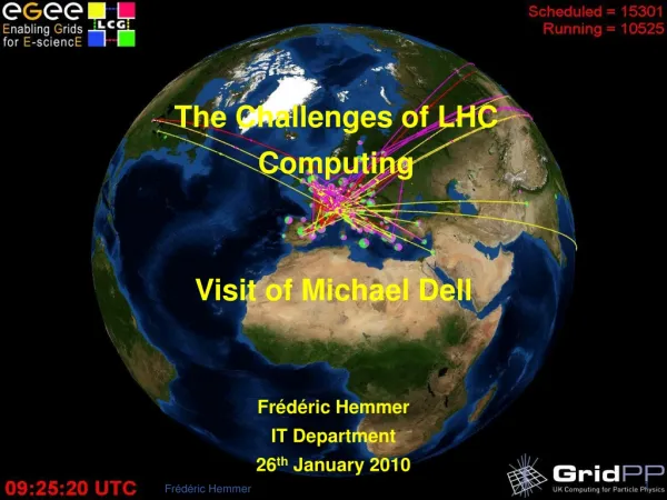
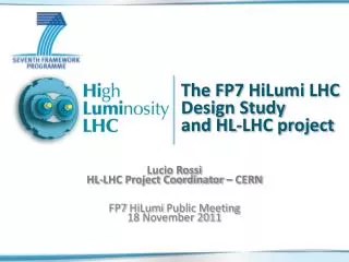
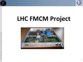
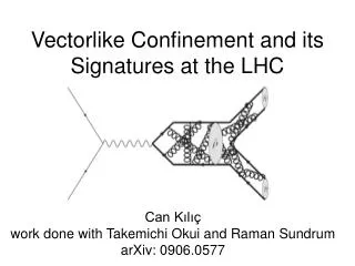
The LHC Project and its Challenges. O. Brüning CERN, Geneva, Switzerland. LHC: A Truly Large Scale Project. Strahl Kollimation. LHCb. CERN Meryn Gelände. Strahl Entsorgung. Atlas. CERN Prevessin Gelände. CMS. Alice. The Installation extends Over two countries, is

E N D
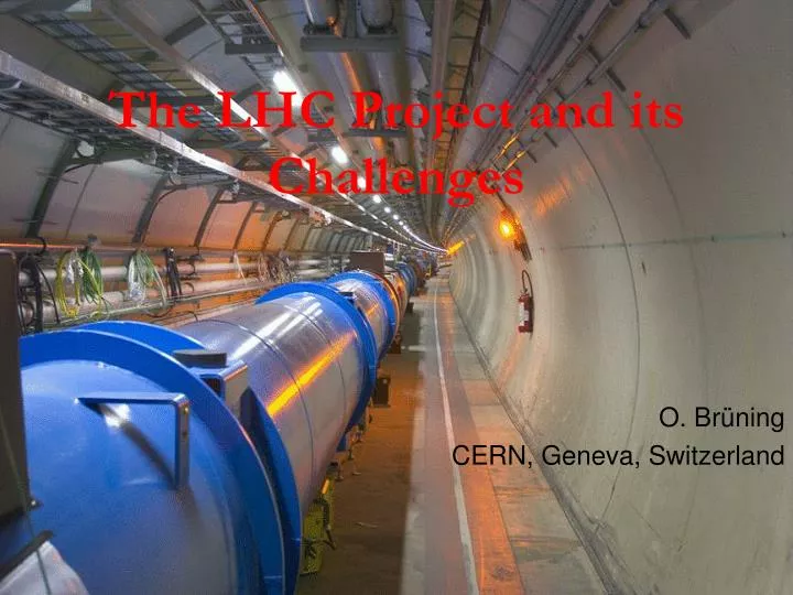
The LHC Project and its Challenges O. Brüning CERN, Geneva, Switzerland
LHC: A Truly Large Scale Project Strahl Kollimation LHCb CERN Meryn Gelände Strahl Entsorgung Atlas CERN Prevessin Gelände CMS Alice The Installation extends Over two countries, is Operated by 20 countries and has a circumference of ca. 27 km HF Strahl Kollimation SLAC Summer Institute; August 2009 Oliver Brüning CERN 2
Introduction Magnet technology Luminosity LHC layout overview Main challenges for the LHC operation LHC parameters Commissioning plan Upgrade options Contents SLAC Summer Institute; August 2009 Oliver Brüning CERN 3
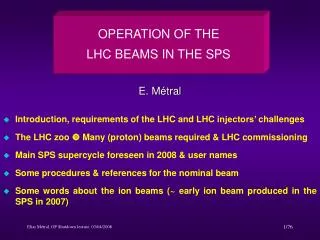
Introduction: LHC Goals & Performance Collision energy: Higgs discovery requires ECM > 1 TeV p collisionsEbeam > 5 TeVLHC: E = 7 TeV Instantaneous luminosity: # events in detector rare events L > 1033cm-2sec-1L = 1034cm-2sec-1 Integrated luminosity: L depends on the beam lifetime, the LHC cycle and ‘turn around’ time and overall accelerator efficiency SLAC Summer Institute; August 2009 Oliver Brüning CERN 4
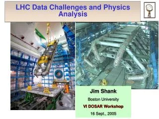
Introduction: the LHC is a Synchrotron R = constant: v = c B LHC / LEP: 0 = 11.3 kHz SLAC Summer Institute; August 2009 Oliver Brüning CERN 5
Introduction: the LHC is a Synchrotron Orbit deviations: e.g. gravitational pull in focusing: linear increase of magnetic fields with deviation resulting Lorentz force equivalent to harmonic oscillator SLAC Summer Institute; August 2009 Oliver Brüning CERN 6
Introduction: the LHC is a Synchrotron Focusing: quadrupole magnets transverse oscillation frequency depends on focal strength! Q = trans oscillation / revolution Alternate gradient focusing: optical telescope beam size depends on focal strength! SLAC Summer Institute; August 2009 Oliver Brüning CERN 7
Introduction: the LHC is a Synchrotron uniform B field: R = constant for E >> E0 realistic synchrotron: B-field is not uniform -drift space for installation -different types of magnets -space for experiments etc high beam energies require: -high magnetic bending field -large circumference -large packing factor SLAC Summer Institute; August 2009 Oliver Brüning CERN 8
Introduction: the LHC is a Synchrotron physics goal: E = 7 TeV existing infrastructure: LEP tunnel: circ = 27 km with 22 km arcs assume 80% of arcs can be filled with dipole magnets: F = 0.8 required dipole field for the LHC: B = 8.38 T (earth: 0.3 10-4 T) SLAC Summer Institute; August 2009 Oliver Brüning CERN 9
Magnet Technology high beam energies require large rings and high fields 1) Iron joke magnet design 2) air coil magnetdesign -field quality given by pole face geometry -field quality given by coil geometry -field amplified by Ferromagnetic material -SC technology avoids Ohmic losses -iron saturates at 2 T -risk of magnet quenches -Ohmic losses for high magnet currents -field quality changes with time SLAC Summer Institute; August 2009 Oliver Brüning CERN 10
Magnet Technology Persistent field errors: change in magnetic flux during acceleration creates loop currents B • Lack of resistive damping in • superconducting cable: • loop currents and their associated • field perturbations • ‘persist’ field errors • contact resistance between cable layers decay of errors -I +I SLAC Summer Institute; August 2009 Oliver Brüning CERN 11
Magnet Technology Persistent field errors: contact resistance between strands -decays with time; -varies between magnets; -average depends on powering history Snap back at acceleration: large field perturbation during short time interval SLAC Summer Institute; August 2009 Oliver Brüning - CERN 12
Magnet Technology Critical surface of NbTi: -high ambient magnetic field lowers the capability to sustain large current densities -low temperatures increase the capability to sustain large current densities -LHC: B = 8.4 T; T = 1.9 K j = 1 - 2 kA / mm2 existing machines: Tev: B=4.5T;HERA: B=5.5T; RHIC: B=3.5T He is superfluid below 2K and has a large thermal conductivity! SLAC Summer Institute; August 2009 Oliver Brüning - CERN 13
Magnet Technology collider ring design requires 2 beams: design with one aperture requires particles & anti-particles Not efficient for a hadron collider! (Tevatron, Chicago USA) 2-ring design implies twice the hardware LHC features novel 2-in-1 magnet design SLAC Summer Institute; August 2009 Oliver Brüning - CERN 14
Magnet Technology 2-in-1 dipole magnet design with common infrastructure: -15 m long few interconnects (high filling factor) but difficult transport (ca. 30 tons) -compact 2-in-1 design allows p-p collisions in LEP tunnel -corrector magnets at ends tight mechanical tolerances SLAC Summer Institute; August 2009 Oliver Brüning - CERN 15
Magnet Technology 15 m long, 30 Ton difficult transport & tight tolerances SLAC Summer Institute; August 2009 Oliver Brüning - CERN 16
Mechanical Technology Aperture tolerances in mm regime! All magnets are bend and have a sagitta (ca. 2cm) Must be geometrically measured! • classification & slot compatibility for installation at critical locations Sortingmagnets during installation: • maximizing physical aperture SLAC Summer Institute; August 2009 Oliver Brüning - CERN 17
Luminosity colliding bunches: with: is determined by the magnet arrangement & powering n is determined by the injector chain goal: high bunch intensity and many bunches small at IP and high collision energy L = 1034 cm-2sec-1 SLAC Summer Institute; August 2009 Oliver Brüning - CERN 18
LHC Layout 2-in-1 magnet design p-p & Pb-Pb collisions 7 TeV p-beam energy > 1 TeV CM energy Higgs discovery 2 high L experiments with L = 1034 cm-2 sec-1 2808 bunches / beam with 1.15 1011 ppb 2 low L experiments: ALICE (Pb-Pb) & LHCb SLAC Summer Institute; August 2009 Oliver Brüning - CERN 19
CMS ATLAS LHCB ALICE Oliver Brüning 20 LHC Layout • built in old LEP tunnel • 8.4 T dipole magnets • 10 GJ EM energy • powering in 8 sectors • 2808 bunches per beam • with 1.15 1011 ppb • 360 MJ / beam • crossing angle & long range beam-beam Combined experiment/ injection regions SLAC Summer Institute; August 2009 Oliver Brüning - CERN 20
Old injector complex and slow ramp (high inductance) Magnetic field perturbations (eddy currents) & resonances Collimation efficiency Beam power and machine protection Collective effects and impedance Beam-beam interaction Triplet aperture and beam-beam Electron cloud effect Main Challenges for the Operation SLAC Summer Institute; August 2009 Oliver Brüning - CERN 21
LHC Challenges: Field Quality & Resonances tune: Q = number of oscillations per revolution resonances: n Qx + m Qy + r Qs = p; “order” = n+m+r Qy Qy Qx Qx complex non-linear dynamics; long term stability (3-body problem) limit for field quality and Q tolerance SLAC Summer Institute; August 2009 Oliver Brüning - CERN 22
Field Imperfections: Super Conducting Magnets time varying field errors in super conducting magnets Luca BotturaCERN, AT-MAS I 11743A 769.1A t 192.1 A SLAC Summer Institute; August 2009
all magnet circuits are tested before and during installation field errors in SC magnets vary with time & operation history adjustments during operation LHC Challenges: Magnet Field Errors the LHC features 112 circuits / beam (+ orbit correctors) non-destructive beam instrumentation SLAC Summer Institute; August 2009 Oliver Brüning - CERN 24
LHC Challenges: Collimation Efficiency Magnet Quench: beam abort several hours of recovery LHC nominal beam intensity: I = 0.5A => 3 1014 p /beam Quench level: Nlost < 7 108 m-1 2.2 10-6 Nbeam! (compared to 20% to 30% in other superconducting rings) • requires collimation during all operation stages! • requires good optic and orbit control! feedback loops SLAC Summer Institute; August 2009 Oliver Brüning - CERN 25
LHC Challenges: Beam Power Magnet quench: • stray particles must not reach the superconducting elements! beam core: 0 to 2 primary beam halo: 2 to 6 s; generated by:non-linearities; noise; IBS etc (can damage equipment) secondary halo: 6 to 8 generated by collimators (quench) tertiary halo: > 8 generated by collimators (save) SLAC Summer Institute; August 2009 Oliver Brüning - CERN 26
LHC Challenges: Beam Power Unprecedented beam power: • potential equipment damage in case of failures during operation • in case of failure the beam must never reach sensitive equipment! SLAC Summer Institute; August 2009 Oliver Brüning - CERN 27
Beam Power and Machine Protection Unprecedented beam power: • all absorbers and the collimation system must be designed to survive an asynchronous beam dump! (total of up to 136 collimators & absorbers) Machine protection System! Robust collimator jaw design • fiber reinforced graphite jaws are more robust than Cu jaws • fiber reinforced graphite has a higher impedance and electrical resistivity SLAC Summer Institute; August 2009 Oliver Brüning - CERN 28
LHC Challenges: Collective Effects resistive wall impedance: • image charges trail behind due to resistivity of surrounding materials Wake fields drive beam instabilities • effect increases with decreasing gap opening of the collimator jaws • impedance of Graphite jaws either limits the minimum collimator opening limit for b* or the maximum beam current phased collimation system for the LHC: • Phase 1: graphite jaws for robustness during commissioning • Phase 2: nominal performance (low impedance, non-linear or feedback) SLAC Summer Institute; August 2009 Oliver Brüning - CERN 29
LHC Challenges: Beam-Beam Interaction beam-beam force: additional focusing for small amplitudes perturbation is proportional to bunch intensity! strong non-linear field: tune & perturbation depends on oscillation amplitude bunch intensity limited by non-linear resonances SLAC Summer Institute; August 2009 Oliver Brüning - CERN 30
LHC Challenges: Beam-Beam Interaction Tune spread due to beam-beam interaction: Tune Footprint: SLAC Summer Institute; August 2009 Oliver Brüning - CERN 31
LHC Challenges: Beam-Beam Interaction LHC working point: n+m < 12 Qx = 64.31; Qy = 59.32 total tune spread must be smaller than 0.015! Qy Qx the LHC features 3 proton experiments with bunch intensity limited by beam-beam force: nominal: N < 1.15 1011 N < 1.5 1011 ultimate: N < 1.7 1011 SLAC Summer Institute; August 2009 Oliver Brüning - CERN 32
LHC Challenges: Triplet Aperture long range beam-beam: Operation with 2808 bunches features approximately 30 unwanted collision points per Interaction Region (IR). • Operation requires crossing angle • aperture reduction! non-linear fields and additional focusing due to beam-beam efficient operation requires large beam separation at unwanted collision points separation of 9 s is at the limit of the triplet aperture for nominal b* values! margins can be introduced by operating with fewer bunches, lower bunch intensities, larger b* values (or larger triplet apertures upgrade studies) SLAC Summer Institute; August 2009 Oliver Brüning - CERN 33
effective cross section LHC Challenges: Crossing Angle geometric luminosity reduction factor: large crossing angle: reduction of long range beam-beam interactions reduction of the mechanical aperture reduction of instantaneous luminosity inefficient use of beam current (machine protection!) SLAC Summer Institute; August 2009 Oliver Brüning - CERN 34
LHC Challenges: Electron Cloud Effect [F. Ruggiero / CERN] SLAC Summer Institute; August 2009 Oliver Brüning - CERN 35
LHC Challenges: Electron Cloud Effect Synchrotron light releases electrons from beam screen: • electrons get accelerated by p-beam impact on beam screen • generation of secondary electrons maxmultiplication; e-cloud heating, instabilities and emittance growth • effect disappears for low bunch currents or large bunch spacing • secondary emission yield decreases during operation (beam scrubbing) [F. Zimmermann / CERN] SLAC Summer Institute; August 2009 Oliver Brüning - CERN 36
Magnetic field perturbations & resonances: beam lifetime Old injector complex and slow ramp: 1h+ between fills Collimation efficiency: losses and magnet quench Beam power and machine protection: 200+damage potential Collective effects and impedance: losses and beam size Beam-beam interaction: lifetime; beam halo and background Triplet aperture and beam-beam: losses & magnet quench Electron cloud effect: heat load on cold bore & instability Main Challenges for the Operation SLAC Summer Institute; August 2009 Oliver Brüning - CERN 37
LHC Operations Cycle SLAC Summer Institute; August 2009 Oliver Brüning - CERN 38 38
Initial Design Parameters SLAC Summer Institute; August 2009 Oliver Brüning - CERN 39
Nominal Parameters SLAC Summer Institute; August 2009 Oliver Brüning - CERN 40
Staged Commissioning Plan for Protons Stage I IV II III No beam Beam Beam Pilot physics run • First collisions • 43 bunches, no crossing angle, no squeeze, moderate intensities • Push performance (156 bunches, partial squeeze in 1 and 5, push intensity 75ns operation • Establish multi-bunch operation, moderate intensities • Relaxed machine parameters (squeeze and crossing angle) • Push squeeze and crossing angle 25ns operation I • Nominal crossing angle • Push squeeze • Increase intensity to 50% nominal 25ns operation II • Push towards nominal performance SLAC Summer Institute; August 2009 Oliver Brüning - CERN 41
Summary Mechanical aperture careful analysis and definition of procedures during installation optimization in Stage I Polarity errors Global magnet field quality & corrector circuit powering Collimation efficiency optimization during Stage I from Stage I to Stage II Beam power and machine protection Collective effects and impedance only at Stage III Triplet aperture and beam-beam only > Stage III Electron cloud effect only at Stage IV SLAC Summer Institute; August 2009 Oliver Brüning - CERN 42
already the nominal LHC operation is very challenging!!! LHC upgrade studies could provide means for overcoming Limitations of nominal configuration R&D results should be available shortly after commissioning! radiation limit of triplet magnets (700fb-1) might be reached by 2013 one needs to prepare a replacement now larger triplet aperture will also reduce collimator impedance! radiation and machine protection issues are very demanding official collaborations for R&D work and machine studies are launchedwithin US−LARP and the European ESGARD initiatives Summary SLAC Summer Institute; August 2009 Oliver Brüning - CERN 43
Upgrade Options CERN identified 3 main options for the LHC upgrade and grouped them according to their impact on the LHC infrastructure into three phases (2001): Phase 0: performance upgrade without hardware modifications Phase 1: performance upgrade with IR modifications Phase 2: performance upgrade with major hardware modifications SLAC Summer Institute; August 2009 Oliver Brüning - CERN 44
Ultimate Parameters (Phase0) SLAC Summer Institute; August 2009 Oliver Brüning - CERN 45
Upgrade Options: Phase 1 increase mechanical aperture of the final focus quadrupoles: • New final focus magnets with larger aperture: • allows smaller b* higher luminosity • larger peak field for constant gradient and higher radiation • a) new magnet technology (Nb3Sn [USLARP]) • b) low gradient final focus layouts (existing NbTi) • implies larger crossing angle • reduction of luminosity SLAC Summer Institute; August 2009 Oliver Brüning - CERN 46
Upgrade Options: Phase 2 CERN identified 3 main areas for consolidation efforts: 1) New Multi Turn Extraction for the PS smaller losses 2) PS magnet renovation and replacement (PS2): program for refurbishing and replacing 50 magnets until 2008 not a long term solution PS2 project 3) replacement for main proton linac: LINAC4 overcomes bottleneck for ‘ultimate’ LHC parameters solves maintenance problem for existing LINAC2 SPL (second phase) could ‘bypass’ PSB (space charge) 4) magnet renovation in the SPS program for refurbishing and replacing SPS magnets CERN ‘White Paper’ SLAC Summer Institute; August 2009 Oliver Brüning - CERN 47
Upgrade Options: Phase 2 White Paper Proton Accelerators for the Future (PAF) study – identified upgrade scenarios • Reliable operation for the LHC (allow ultimate LHC beam) • Options for future programs Linac2 (1980) Linac4 50 MeV 160 MeV PSB (1972) SPL’ RCPSB SPL 1.4 GeV ~ 5 GeV PS (1959) SPL: Superc. Proton Linac (~ 5 GeV) SPL’: RCPSB injector (0.16 to 0.4-1 GeV) RCPSB: Rapid Cycling PSB (0.4-1 to ~ 5 GeV) PS2: High Energy PS (~ 5 to 50 GeV – 0.3 Hz) PS2+:Superconducting PS (~ 5 to 50 GeV – 0.3 Hz) SPS+: Superconducting SPS (50 to1000 GeV) SLHC: “Superluminosity” LHC (up to 1035 cm-2s-1) DLHC: “Double energy” LHC (~14TeV) 26 GeV PS2 (PS2+) Output energy 40 – 60 GeV SPS(1976) SPS+ 450 GeV 1 TeV LHC / SLHC DLHC 7 TeV ~ 14 TeV From: PAF study group, in particular R.Garoby SLAC Summer Institute; August 2009 Oliver Brüning - CERN 48