Download
1 / 20
200 likes | 311 Views
Gamma-ray Large Area Space Telescope. GLAST Large Area Telescope: Mechanical Systems Peer Review March 27, 2003 Section 7.1 – Stress Analysis Marc Campell SLAC Mechanical Systems Mgr. marcc@slac.stanford.edu. Topics. Agenda Cal-Grid interface load recovery Grid Stress analysis

E N D
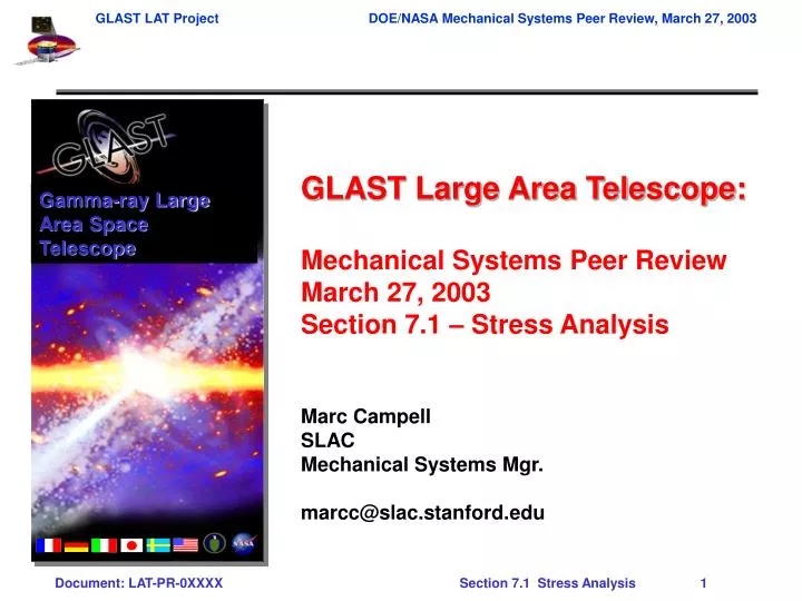
Gamma-ray Large Area Space Telescope GLAST Large Area Telescope: Mechanical Systems Peer Review March 27, 2003 Section 7.1 – Stress Analysis Marc Campell SLAC Mechanical Systems Mgr. marcc@slac.stanford.edu
Topics Agenda • Cal-Grid interface load recovery • Grid Stress analysis • Radiator Mount Bracket analysis • Further work
CAL Interface Load Recovery • CAL-Grid bolted friction joint • 1152 screws (72 per CAL module) • Joint allows CAL bottom plate to stiffen LAT by closing out bottom side of Grid • Load recovery • Interface loads are backed out from the FEA model by resolving nodal forces at the interface into shear and normal loads at the bolt locations • Required friction coefficients are generated, given a set screw preload and a perimeter backing strip • EM bolted joint tests are underway to validate friction coefficient and joint behavior Histogram Showing Required Friction Coefficients Qual Friction Coefficients for CAL-Grid Joint
Friction Coefficient Data for Bay13 With Perimeter Backing Plates SC Interface
Grid Stress Analysis • Grid stress analysis indicates positive margins of safety for all regions • Highest stresses occur in transition regions around SC mount • Nominal maximum Von Mises stress is order of magnitude below yield for material • Large corner radii in the actual design, not included in the model, limit stress risers • Top flange in model has a weighted-average cross section which is no more than twice the minimum cross sectional area • Grid material properties • Material: 6061-T6 aluminum (6061-T651, stress-relieved, then heat-treated during fabrication) • Sy = 240 MPa (35 ksi) • Su = 290 MPa (42 ksi) • Factors of safety (per NASA-STD-5001) • Metallic structures • Yield: FSy = 1.25 • Ultimate: FSu = 1.4
Grid Stress Analysis MSy = Sy/(1.25 si) –1 MSu = Su/(1.4 si) –1
Grid Internal Stresses • Grid internal bending stresses are low, as indicated in contour plots lat9ol6 lat9ol7 Y-Direction Direct Stress in Web Near +Y SC Mount for Lift-Off/Airloads Case Y-Direction Direct Stress in Web Near Grid Center for MECO Case
Grid Stresses Near SC Mount Boss lat9ol7 lat9ol6 Von Mises Equivalent Stress for MECO Case Von Mises Equivalent Stress for Lift-Off/Airloads Case
Radiator Mount Bracket Analysis • Design Loads and critical load cases • Loads defined in Environmental Spec • FS=1.25 (PFQ) used for launch loads • FS=1.40 used for lift case • Assume Observatory lift load is carried in 2 of 4 fittings • Critical Load Cases Studies
Finite Element Model:Parameters and Assumptions • Mass Properties • MSS States Maximum Observatory mass of 4627 kg + PAF • Bracket mass calculated to be 5.56 kg • Material Properties • AL 6061-T6 • Elastic Modulus = 68.9 GPa (10 Msi) • Poisson’s Ratio = 0.33 • Density = 2710 kg/m3 (0.10 lb/in3) • Yield Stress = 241 MPa (35 ksi) • Shear Ultimate = 145 MPa (21 ksi) • Bearing Yield = 345 MPa (50 ksi, 1.5 e/d)
Results – Stress Contours: Case +X / -Z Load Max Von Mises Stress =17.0 MPa (2.46 ksi) (Uncertainty = 2.0) Material Yield =241 MPa (35.0 ksi) M.S. = 13.2
Results – Stress Contours:Case -X / -Z Load Max Von Mises Stress =18.1 MPa (2.62 ksi) (Uncertainty = 2.0) Material Yield =241 MPa (35.0 ksi) M.S. = 12.4
Results – Stress Contours:Case +Y / -Z Load Max Von Mises Stress =8.6 MPa (1.24 ksi) (Uncertainty = 2.0) Material Yield =241 MPa (35.0 ksi) M.S. = 28.2
Results – Stress Contours:Case -Y / -Z Load Max Von Mises Stress =6.6 MPa (0.96 ksi) (Uncertainty = 2.0) Material Yield =241 MPa (35.0 ksi) M.S. = 36.5
Results – Stress Contours:Case +Z Lift Load Max Von Mises Stress =188.9 MPa (27.4 ksi) (Uncertainty = 2.0) Material Yield =241 MPa (35.0 ksi) M.S. = 0.28
Tension Failure Bearing Failure Tear Out Failure Summary of Margins of Safety 27 26 14 25 15 12 11 16 13 22 23 24
RMB Conclusions • Lift case induces the highest stresses • Margins of safety are good for all design cases • Calculated stiffness is high, which is conservative for loads determination • The radiator attachment bracket meets or exceeds all design requirements
Summary and Further Work • Summary • Integrated LAT structural analysis results of the static-equivalent load cases indicate that LAT deflections and stresses are within required limits • Grid stress analysis shows that the Grid design is not highly-stressed, but driven more by the natural frequency requirement • Further work • Finalize design of the SC mount region with the SC contractor and complete stress analysis • Complete stress analysis on EMI skirt pieces
End of Section 7.1