Download
1 / 32
330 likes | 589 Views
Transmission Line with Change of Z o. Consider a composite transmission line made up of two sections: a section with characteristic impedance Z 1 , followed by an infinite line with characteristic impedance Z 2 :. I 1 + LINE 1 I 1 - x = 0 LINE 2. I 2 +.

E N D
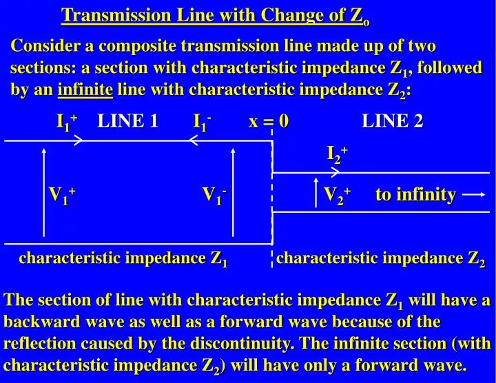
Transmission Line with Change of Zo Consider a composite transmission line made up of two sections: a section with characteristic impedance Z1, followed by an infinite line with characteristic impedance Z2: I1+ LINE 1 I1- x = 0 LINE 2 I2+ V1+ V1- V2+ to infinity characteristic impedance Z1 characteristic impedance Z2 The section of line with characteristic impedance Z1 will have a backward wave as well as a forward wave because of the reflection caused by the discontinuity. The infinite section (with characteristic impedance Z2) will have only a forward wave.
Forward waves V1+ = Vi e-g1x ejwt on line 1 I1+ = (Vi /Z1) e-g1x ejwt (Ii = Vi/Z1) Reflected waves V1- = Vr e+g1x ejwt on line 1 I1- = (Vr/Z1) e +g1x ejwt (Ir = Vr/Z1) Forward wave V2+ = Vt e-g2x ejwt on line 2 I2+ = (Vt /Z2) e-g2x ejwt (It = Vt/Z2)
At the junction between the lines (x = 0) there must be continuity of current and voltage: LINE 1 I1+ - I1- = I2+LINE 2 V1+ + V1- = V2+ to infinity x = 0 Inserting the expressions for V1+ etc. and putting x = 0: Vt = Vi + Vr (1) It = Ii – Ir (2) But each of the current waves can be expressed in terms of the corresponding voltage waves and characteristic impedance, so (2) can be re-written as Vt /Z2 = Vi /Z1 - Vr /Z1 (3)
Eliminating Vt between equations (1) and (3) Vi + Vr = (Vi - Vr)Z2/Z1 => Vi (1 - Z2/Z1) = -Vr (1 + Z2/Z1) => Vr /Vi = r = -(1 - Z2/Z1)/(1 + Z2/Z1) = (Z2 - Z1)/(Z2 + Z1) But an infinite line of characteristic impedance Z2 is equivalent to a load Z2 as far as the "source" (i.e. line 1) is concerned: Z1 Z2 Z1 Z2 infinite Zo ZL So for a line of characteristic impedance Zo connected to a load ZL: r = (ZL - Zo)/(ZL + Zo)
Vr /Vi = r = (ZL - Zo)/(ZL + Zo) The voltage reflection coefficient, r, relates the reflected voltage wave to the incident voltage wave and hence is a measure of the discontinuity seen by the transmission line at the load. Note that: (1) r is a complex number if ZL (or Zo) is complex (Zo is, however, real for a lossless line). Hence r contains both magnitude and phase information: r = |r|ejf |r| is the magnitude of the reflection coefficient f is the phase of the reflection coefficient (2) The magnitude of r varies between 0 and 1 for all values of ZL between 0 and ∞.
RATIO OF V-/V+AT AN ARBITRARY DISTANCE l FROM THE LOAD ZL So far, we have derived an expression for V-/V+ at the load, which is taken to be at x = 0. But we can define V-/V+ at an arbitrary distance from the load, i.e. we can work it out for a load-and-line combination. So what is V-/V+ at a distance l down the line in front of the load, i.e. at x = -l ? Zo ZL x = -l x = 0 Forward Wave: V+ = Vi e-gx ejwt Backward Wave: V- = Vr e+gx ejwt => V-/V+= r-l = Vr e-gl ejwt/Vi e+gl ejwt = (Vr/Vi e-2gl) = re-2gl (since Vr/Vi = r)
If the line is lossless gl = jbl , hence: r-l= re-2gl =re-j2bl= |r|ejfe-j2bl = |r|ej(f-2bl) (compare with r = |r|ejf) i.e. the magnitude of the reflection coefficient at x = -l is the same as at x = 0 but its phase changes from f to f - 2bl . An additional phase change of -2bl has been added by the introduction of the length of line, l . This is a very important result for the Smith Chart, which we will be looking at later on.
Part 2 - Characteristic Impedance and Reflections Lecture Topics 4. Current and voltage on a transmission line: Characteristic impedance, ZO Characteristic impedance of lossless lines Characteristic impedance of general lines Infinitely long transmission lines Reflections on transmission lines 5. Transmission line with change of ZO: voltage reflection coefficient Voltage reflection coefficient at an arbitrary distance l from the load ZL 6. Impedances of terminated lines Voltage Standing Wave Ratio (VSWR) Voltage Standing Wave measurement
Example 4.5 - Current and voltage at the load for a matched transmission line. The secondary line constants at 796 Hz for a particular transmission line 300 km long are: α= 7.84x10⁻³ Np km-1 = 2.87x10⁻² rad km-1 Zo = 689 - j175 Ω The line is terminated by a load with impedance equal to Zo and a generator is connected to the sending end. If the generator has an internal resistance of 600 Ω and voltage amplitude 2V, what is the current and voltage at the load?
IMPEDANCES OF TERMINATED LINES In this section we want to find an expression for the impedance of a load and line combination: Zin = ? Zo ZL • For a transmission line with a mismatched load (i.e. with ZLg Zo) there will be reflected current and voltage waves as well as the forward waves. • The impedance of the load and line combination as seen by the source will be the ratio of VT/IT at the input terminals of the line: Zin = VT/IT = (V+ + V-)/(I+ - I-) (at the input end)
Zin = VT/IT = (V+ + V-)/(I+ - I-) (at the input end) So Zin will depend on the magnitude and phase of the reflected waves (V-, I-) when they reach the source, which will depend on… • how much of the incident waves (V+, I+) are reflected by the load • and on the phase change introduced by the reflection process i.e. it will depend on r • It will also depend on the length of the line (e.g. phase change over length l is bl )
I I+ I- Zin = V/I V V+ Zo V- ZL x = -l x = 0 Take the load to be at x = 0 and the input to be at x = -l (this allows the forward wave to propagate in the +ve x direction). VT = V+ + V- = Vi e-gxejwt + Vr e+gxejwt => VT = Vi e-gxejwt + rVi e+gxejwt (since Vr / Vi = r) Hence the voltage at the input end of the line (i.e. at x = -l ) is: V-l = Viejwt (egl+ re-gl)
V-l = Viejwt(egl + re-gl ) Similarly, the total current at any point on the line will be: IT = I+ - I- = Ii e-gx ejwt - Ire+gxejwt => IT = (Vi/Zo) e-gxejwt - (Vr/Zo) e+gx ejwt = (Vi/Zo) e-gxejwt - r(Vi/Zo) e+gx ejwt (since Vr / Vi = r) Hence the current at the input end of the line (i.e. at x = -l ) is: I-l = (Vi/Zo) ejwt(egl- re-gl )
Suppose we are dealing with a matched load… …for a matched load, r = 0, hence: I+ Zin = Zo V+ Zo Zo x = -l x = 0
Because of the relations between the hyperbolic functions [sinh(x), cosh(x) and tanh(x)] and the exponential function we can write the expression for Zin in two other equivalent forms. Using these relationships and the equation relating the voltage reflection coefficient to ZL and Zo
…. we can express Zin as: or: Original expression: All three expressions are equivalent – which one you use depends on whether you know ZL or ρ.
In the case of a lossless line a = 0, so g = a + jb = jb and is purely imaginary, so the hyperbolic functions reduce to trigonometric functions: Zin becomes: or: Original expression:
Example 5.1 - Impedance of a load and line combination. A 1m long, air-spaced transmission line with Zo = 50Wis terminated by a load of 40W. Calculate the input impedance, Zin, of the combined load and line at frequencies of 30 MHz, 75 MHz and 300 MHz, assuming the line is lossless.
3. N.B. Zo is NOT the impedance you would measure simply by connecting the line to an impedance measuring system – this would give you the open-circuit impedance Zoc. We will see later (Example 5.2) that Zo = (ZocZsc)1/2 where Zsc is the short-circuit impedance.
Example 5.2 - Characteristic impedance in terms of the open-circuit and short-circuit impedances. Find an expression relating the characteristic impedance Zo to the open-circuit and short-circuit impedances (Zoc, Zsc) of a transmission line.
This link runs the Animation Standing_waves_x
Instantaneous total voltage Reflected wave voltage Incident wave voltage Extreme 1 Cancellation Extreme 2 reflected waveincident wave Instantaneous total voltage Reflected wave voltage Incident wave voltage Instantaneous total voltage Reflected wave voltage Incident wave voltage
Voltage envelope = standing wave t = time t = t1 t = t2 t = t3 Vr = Vi x |V| minimum (|V|=0) |V| maximum The standing wave shows how the AMPLITUDE, |V|, of the oscillations in the total voltage varies with distance, x.
Voltage envelope = standing wave Vr < Vi t = time t = t1 t = t2 t = t3 x |V| minimum If the reflected wave has a smaller amplitude than the incident wave, complete cancellation cannot occur - the standing wave does not drop to zero at the minima.
Summary q The impedance of a load and line combination is given by: or: or:
q For a lossless line the hyperbolic functions can be replaced by trigonometric functions: or: or:
Incident and reflected voltage waves superimpose and give rise to a regular variation in the voltage amplitude with distance along the line, i.e. they give rise to VOLTAGE STANDING WAVES. (The same is also true of the current.) Vr < Vi
Summary q The impedance of a load and line combination is given by: or: or:
q For a lossless line the hyperbolic functions can be replaced by trigonometric functions: or: or: