Download
1 / 51
510 likes | 618 Views
Overview of Database Design. By Nazife Dimililer. Database Management System. A DBMS is a data storage and retrieval system which permits data to be stored non-redundantly while making it appear to the user as if the data is well-integrated. Application #1. Application #2. Application #3.

E N D
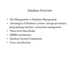
Overview of Database Design By Nazife Dimililer
Database Management System A DBMS is a data storage and retrieval system which permits data to be stored non-redundantly while making it appear to the user as if the data is well-integrated.
Application #1 Application #2 Application #3 DBMS Database containing centralized shared data Database Management System DBMS manages data resources like an operating system manages hardware resources
Advantages of Database Approach • Program-Data Independence • Metadata stored in DBMS, so applications don’t need to worry about data formats • Data queries/updates managed by DBMS so programs don’t need to process data access routines • Results in: increased application development and maintenance productivity • Minimal Data Redundancy • Leads to increased data integrity/consistency
Advantages of Database Approach • Improved Data Sharing • Different users get different views of the data • Enforcement of Standards • All data access is done in the same way • Improved Data Quality • Constraints, data validation rules • Better Data Accessibility/ Responsiveness • Use of standard data query language (SQL) • Security, Backup/Recovery, Concurrency • Disaster recovery is easier
Costs and Risks of the Database Approach • Up-front costs: • Installation Management Cost and Complexity • Conversion Costs • Ongoing Costs • Requires New, Specialized Personnel • Need for Explicit Backup and Recovery • Organizational Conflict • Old habits die hard
The Range ofDatabase Applications • Personal Database – standalone desktop database • Workgroup Database – local area network (<25 users) • Department Database – local area network (25-100 users) • Enterprise Database – wide-area network (hundreds or thousands of users)
Evolution of DB Systems • Flat files - 1960s - 1980s • Hierarchical – 1970s - 1990s • Network – 1970s - 1990s • Relational – 1980s - present • Object-oriented – 1990s - present • Object-relational – 1990s - present • Data warehousing – 1980s - present • Web-enabled – 1990s - present
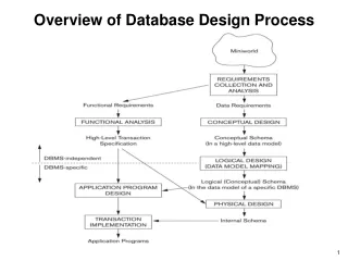
Database Design Phases • Conceptual Design Model the data without any physical considerations for each user view. • Logical Design Choose the data model that will be used and modify the conceptual data model to fit the data model without any other physical considerations. Validate the model using normalization and transaction requirements. • Physical Design Choose the actual DBMS and implement the data model efficiently. Performance, security and reliability are key issues.
Physical Database Design • Purpose - translate the logical description of data into the technical specifications for storing and retrieving data • Goal - create a design for storing data that will provide adequate performance and insure database integrity, security and recoverability
Inputs Decisions • Normalized relations • Volume estimates • Attribute definitions • Response time expectations • Data security needs • Backup/recovery needs • Integrity expectations • DBMS technology used • Attribute data types • Physical record descriptions (doesn’t always match logical design) • File organizations • Indexes and database architectures • Query optimization Leads to Physical Design Process
Designing Fields • Field: smallest unit of data in database • Field design • Choosing data type • Coding, compression, encryption • Controlling data integrity
Field Data Integrity • Default value - assumed value if no explicit value • Range control – allowable value limitations (constraints or validation rules) • Null value control – allowing or prohibiting empty fields • Referential integrity – range control (and null value allowances) for foreign-key to primary-key match-ups
Denormalization • Transforming normalized relations into unnormalized physical record specifications • Benefits: • Can improve performance (speed) be reducing number of table lookups (i.e reduce number of necessary join queries) • Costs (due to data duplication) • Wasted storage space • Data integrity/consistency threats • Common denormalization opportunities • One-to-one relationship • Many-to-many relationship with attributes • Reference data (1:N relationship where 1-side has data not used in any other relationship)
Project Identification and Selection Project Initiation and Planning Analysis Logical Design Physical Design Implementation Maintenance Systems Development Life Cycle
Systems Development Life Cycle Project Identification and Selection Purpose --preliminary understanding Deliverable –request for project Project Initiation and Planning Analysis Database activity – enterprise modeling Logical Design Physical Design First step in database development Specifies scope and general content Overall picture of organizational data, not specific design Entity-relationship diagram Descriptions of entity types Relationships between entities Business rules Implementation Maintenance
Systems Development Life Cycle Project Identification and Selection Purpose – state business situation and solution Deliverable – request for analysis Project Initiation and Planning Analysis Logical Design Physical Design Database activity – conceptual data modeling Implementation Maintenance
Systems Development Life Cycle Project Identification and Selection Purpose –thorough analysis Deliverable – functional system specifications Project Initiation and Planning Analysis Logical Design Physical Design Database activity – conceptual data modeling Implementation Maintenance
Systems Development Life Cycle Project Identification and Selection Purpose –information requirements structure Deliverable – detailed design specifications Project Initiation and Planning Analysis Logical Design Physical Design Database activity – logical database design Implementation Maintenance
Systems Development Life Cycle Purpose –develop technology specs Deliverable – program/data structures, technology purchases, organization redesigns Project Identification and Selection Project Initiation and Planning Analysis Logical Design Physical Design Database activity – physical database design Implementation Maintenance
Systems Development Life Cycle Purpose –programming, testing, training, installation, documenting Deliverable – operational programs, documentation, training materials Project Identification and Selection Project Initiation and Planning Analysis Logical Design Physical Design Database activity – database implementation Implementation Maintenance
Systems Development Life Cycle Project Identification and Selection Purpose –monitor, repair, enhance Deliverable – periodic audits Project Initiation and Planning Analysis Logical Design Physical Design Database activity – database maintenance Implementation Maintenance
Simplified Database Development Procedure Start Draw ERD Convert to Relational Schema Validate using Normalization Validate against user transactions Stop
Some helpful pointers • Use consistent naming rules for all entities,relationships and attributes • Choose primary keys intelligently. Primary keys should NOT change over time. • Choose appropriate data types for attributes
Introduction • There are endless possibilities for a designer to make a bad or wrong choice. • You must try to understand how the customer manipulates data and how the ERD will produce the data structures required to sustain the same data manipulation • The errors may be corrected at conceptual or logical database design phases. In fact you must check for errors at every phase! • Here we discuss how to fix some common problems at the conceptual database design phase.
Id Name FormNo FormDate First_inspection Coordinator_Approval Restaurant TextBook_ Request Second_inspection Director_Approval Third_inspection Rector_Approval Problem:Unnormalized Attributes • Does an attribute name contain data? • Multiple Attributes:ex : A1, A2, A3, …, An ex :First_Inspection, Second_Inspection … • Enumerations:X-Approval, Y-Approval, Z-Approval • Difficult to predict population and changes require attribute changes
Id Name First_inspection OrderNo Result Name Id Restaurant Second_inspection Restaurant inspection Third_inspection Solution: Unnormalized AttributesFixing Repeating Attributes • Split repeating variables into its own • Split into a repeating group based on indexex: (A,n) , (InspectionResult, OrderNo)
OrderNo Id Name Result Restaurant Inspection Inspection belongsTo performedBy employee Id Name Solution: Unnormalized AttributesFixing Repeating Attributes • Alternatively the following solution may be used If we need to store information on the employees who performed the inspection, it can be easily added here
EntryDate FormNo FormDate Coordinator_Approval Code Status FormDate FormNo TextBook_ Request Director_Approval TextBook_ Reuest Approval Rector_Approval Solution: Unnormalized Attributes Fixing Enumerations • Enumerations • Split the enumeration to code and domain value(Code, Approval)
EntryDate FormNo Code FormDate Status TextBookRequest Inspection Approval Has FormNo FormDate Name EntryDate Id Status TextBookRequest Employee Approval Has FormNo FormDate EntryDate Name Status Id TextBookRequest Inspection Employee Approval Has Solution: Unnormalized Attributes Fixing Enumerations Alternatively We can find out exactly who approved or disapproved of a text book request Better Yet: Or
Problem: Enumerations (Lists) • Does an entity have any attributes that are enumerations but are not foreign keys? • Create special code entities to hold the list of enumerated values and descriptions– also known as Lookup Tables, Reference tables or Cross-Reference entities • This is different from the unnormalized attribute-enumartions. Here the attribute name does not contain data! • Ex: If country is a simple attribute, then its value must be chosen from a list.
id name id name Student Student country name isFrom Country id name Code Employee Employee isFrom country id name Solution: Use Validation Entities (lookup tables)
Id Name Instructor Id Name Instructor change Title InstructorTitle InstructorTitle Title ChangeDate Problem : Single valued attributes changing over time • Even though an attribute may have only one value at any given time, do you need to know its previous values? • Do you need to keep track of changes of an attribute? Solution: Add History At any given time an instructor has only one title: Assist. Prof, Assoc. Prof, Prof. But the title is expected to change!
EquipmentId ServiceDate EquipmentId ServiceDate ServiceRecord Description ServiceRecord performs Description Employee Employee HiredateDate Salary Id Name Problem: Use of “complex” attributes • Does an attribute represent a real life object or concept? Solution: Create a separate entity for the “complex” attribute
city street country firstname lastname address name address name Customer Customer Id Id Representing compound attributes as simple attributes • Is a simple attribute composed from more than one field? Solution: Use composite attributes
Problem: Fan Traps • Result of hierarchical relationships that split semantic relationships resulting in the loss of information • Commonly expressed by traversals from weak entity to related weak entity through parent which results in loss of information • Fixed by reordering hierarchy
code speed officeno name Office Employee Computer contains worksin ramcapacity id floor Example of Fan Trap Issue: Who uses which computer?
worksin uses Fixing a Fan Trap speed cid ramcapacity officeno id name Employee Office Computer floor This re-arrangement fixes the fan trap problem but if it is possible to have a computer in an office that is not assigned to any employee, it has another problem
Problem: Chasms • Result of hierarchical relationships that split semantic relationships resulting in the loss of business rules • Commonly expressed by creating artificial intermediate entity values for the sole purpose of providing a link • Fixed by rebalancing hierarchy and adding appropriate relationships
name code name eid cid name Branch employee customer (0,M) (1,1) (0,M) (0,1) worksFor represents Example of a Chasm Issues: What if a customer is not assigned to an employee?
dealsWith worksFor represents Fixing a Chasm name code name eid cid name Branch employee customer (0,M) (1,1) (0,M) (0,1) (1,1) (0,M)
More Design problems • Misplaced relationships • Incorrect Cardinalities • Missing Relationships • Overuse of specialized data modeling tools (ex: Inheritance, multiway relationships) • Redundant Relationships
Use of Intelligent vs Surrogate Keys • A surrogate key is an artificial or synthetic key that is used as a substitute for a natural key aka intelligent key. • "Surrogate key" may also be known as "System-generated key", "Database Sequence number", "Synthetic key", "Technical key" or an "Arbitrary, unique identifier". • primary keys are hard to change. • Intelligent keys suffer from this problem because not only are they used as primary and foreign keys but they also have some business meaning associated with them • The biggest advantage for intelligent keys is that users understand what they mean whereas surrogate keys don't make any business sense. Data Models that use surrogate keys usually have more normalization errors.
Natural keys: are more logical can sometimes can mean fewer joins help to encourage good modeling are traditional/user friendly make snooping around in the data easier Surrogate keys: are shorter are easier to join take less storage enable natural key fields to be easily changed are what Object Oriented (and object relational) databases use Surrogate vs. Intelligent Keys
Goals of Database Development • Develop a Common Vocabulary • Define the meaning of Data • Ensure Data Quality • Find an Efficient Implementation