Download
1 / 28
290 likes | 442 Views
Improvements on FRAPCON3 and FRAPTRAN Mechanical Modelling. Arttu Knuutila, Seppo Kelppe SAFIR-PUOLIVÄLISEMINAARI 20.-21.1.2005. Introduction and Contents. Description of elaborations on fuel mechanical modelling made under a one-year attachment to PNNL Laboratory in the US Contents

E N D
Improvements on FRAPCON3 and FRAPTRAN Mechanical Modelling Arttu Knuutila, Seppo Kelppe SAFIR-PUOLIVÄLISEMINAARI 20.-21.1.2005
Introduction and Contents • Description of elaborations on fuel mechanical modelling made under a one-year attachment to PNNL Laboratory in the US • Contents • Introduction to requirements of modelling the mechanical behaviour in a fuel rod • Summary description of the refined FEM approach • Examples of verification
Basic construction of a fuel rod • TYPICALLY: • Cladding material: various zirconium alloys • Diameter ~ 9mm • Length 2500-3500 mm • Fill gas: Helium to 0.6-1.5 MPa
Large Clad Deformations in a LOCA test • a) Säteilytetty sauva • polttoainemuruja pullistumassa • b) Tuore suojakuoriputki • säteilytetystä poikkeava halkeaman muoto • Muodonmuutokset samankaltaiset - säteilyvauriot pääosin hehkuttuneet pois (?)
Different Clad Performance Scenaria in a RIA Transient Failure model Ballooning model Dispersed Fuel to Water Interaction
Clad Failure Modes in a RIA • Competing Mechanisms • Early PCMI Failure • DNB - High Temperature - Ballooning and Burst - Oxidation and Embrittlement
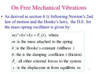
FRAPCON3 Steady-state fuel performance code Capable of modelling fuel thermal-mechanical behaviour of and fission gas release in a LWR fuel rod during normal operations Validated up to 65 MWd/kgU burnup FRAPTRAN Transient fuel performance code Capable of analysing thermal mechanical behaviour of a LWR fuel rod in reactivity accidents, loss-of-coolant accidents, or anticipated transients without scram Validated up to 65 MWd/kgU burnup USNRC steady-state and transient codes
FRAPCON3/FRAPTRAN mechanical modelling • Both codes employ a rather simple stress-strain modelling for the cladding called FRACAS I that originates from the development work done in the 70s • FRACAS I uses a 1D thin shell model for the cladding stress-strain analysys, where the fuel rod is divided into axial slices and each slice has its own separate 1D mechanical solution • FRACAS I can model pressure loaded cladding (open gap) or PCMI loaded cladding (closed gap) with solid contact, i.e. it does not allow slippage between the fuel pellet stack and the cladding if the gap is closed • FRACAS I does not include stress-strain analysis for the fuel pellet stack
New mechanical modelling • a stress-strain analysis option with finite element model has been implemented in FRAPCON3/FRAPTRAN codes • 1½D, 2D, and 3D analysis capability • capability of modelling large strains and displacements, e.g. localized deformations can be modelled • Modelled deformation mechanisms • Elasticity with nonlinear hyperelastic model • Large strain plasticity with J2 flow theory (von Mises) and isotropic hardening • Creep, a time dependent extension to the J2 flow theory • Thermal dilation and irradiation growth • Dilation of ideal gas • 1½D and 2D contact with friction (Coulomb friction model)
1½D, 2D, and 3D elements • 1½D axisymmetric linear, 2D axisymmetric bilinear, and 3D trilinear solid elements with mean dilation formulation • 1½D and 2D contact interface with Coulomb friction with penalty method • 1½D axisymmetric, 2D axisymmetric, and 3D gas cavities with ideal gas
Efficient sparse matrix solver • Efficient sparse matrix solution by using matrix reordering to reduce the matrix profile and direct solution methods, LU and LDLT factorisations • An example of a stiffness matrix where the memory space needed for the matrix factorisation is reduced by 70% by reordering
LARGE STRAIN MODELLING • Capability to model localized deformations. For example ballooning of the cladding during loss-of-coolant accident
Pellet cladding contact with Coulomb friction • Coulomb friction t < p solid contact t = p sliding with friction Where t is tangential traction, p is contact pressure, and is friction coefficient
Verification of FE modelling • Patch tests to verify the element performance and correctness even in badly distorted element mesh • Extensive verification for large strain elasto-plasticity with verification cases that have an analytical solution or reference solution in the literature • An example of large strain verification case, a compressed billet
Conclusion • Modelling elaborations to the USNRC fuel performance codes FRAPCON and FRAPTRAN that significantly improve provisions of more detailed analyses of rod mechanical behaviour were introduced and taken into use • 2-D and 3-D descriptions were made available through advanced FEM formulation • Bases for covering crucial detail as frictional pellet-to-clad contact, pellet and clad creep-plastic deformation, and large-deformation ballooning were laid • Modularity and flexibility were among the goals - Results will be readily applicable in other analytical environments • Verification of formulation confirms robust numerical performance and improved representativity to real-life behaviour • Validation and applications now (early 2005) in progress