Download

1 / 31
370 likes | 581 Views
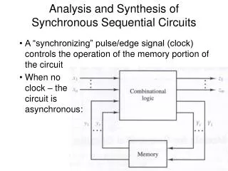
Synchronous Sequential Circuit Analysis. Combinational circuit. Outputs. State Memory. Inputs. Clock. Synchronous Sequential Circuit. State Memory – A set of n edge-triggered flip-flops that store the current state of the machine

E N D
Combinational circuit Outputs State Memory Inputs Clock Synchronous Sequential Circuit • State Memory – A set of n edge-triggeredflip-flops that store the current state of the machine • All flip-flops are triggered from the same master clock signal • All change state together • Combinational circuit • Next state logic • Output logic – Mealy and Moore Next State Current State
Mealy Model next state = F (current state, inputs) outputs = G (current state, inputs)
Moore Model next state = F (current state, inputs) outputs = G (current state)
Analysis - Goals • Characterize as Mealy or Moore machine • Determine nextstate equations, i.e., find the function F • next state = F (current state, inputs) • Determine output equations • Meally: outputs = F (current state, inputs), or • Moore: outputs = F (current state) • Express as machine behavior • Statetable, or • State diagram • Formulate English description of machine behavior
An example sequential circuit • A sequential circuit with two JK flip-flops • State or memory: Q1Q0 • One input: X; One output: Z
Output Equations • From the diagram, you can see that Z = Q1Q0X Mealy model circuit !!!
Next State Equations – Q(t+1) • Find the flip-flop input equations/excitation equations • Substitute excitation equations in the flip-flop’s characteristic equation J1 = X’ Q0 K1 = X + Q0 J0 = X + Q1 K0 = X’
Next State Equations – Q(t+1) • Next state equations: • Q1(t+1) = K1’Q1(t) + J1Q1’(t) = (X + Q0(t))’ Q1(t) + X’ Q0(t) Q1’(t) = X’ (Q0(t)’ Q1(t) + Q0(t)Q1(t)’) = X’ (Q0(t) Q1(t)) • Q0(t+1) = K0’Q0(t) + J0Q0’(t) = X Q0(t) + (X + Q1(t)) Q0’(t) = X + Q0(t)’ Q1(t) • Excitation equations: • J1 = X’ Q0and K1 = X + Q0 • J0 = X + Q1and K0 = X’ • Characteristic equation of the JK flip-flop: • Q(t+1) = K’Q(t) + JQ’(t)
State Table & Next State Equations • Q1(t+1) = X’ (Q0(t) Q1(t)) • Q1=0, Q0=0, X= 0 => Q1(t+1)= 0 • Q0(t+1) = X + Q0(t)’ Q1(t) • Q1=0, Q0=0, X= 0 => Q0(t+1)= 0 0 0
State Table & Next State Equations • Q1(t+1) = X’ (Q0(t) Q1(t)) • Q1=0, Q0=1, X= 1 => Q1(t+1)= 0 • Q0(t+1) = X + Q0(t)’ Q1(t) • Q1=0, Q0=1, X= 1 => Q0(t+1)= 1 0 0 0 1
State Table & Next State Equations • Q1(t+1) = X’ (Q0(t) Q1(t)) • Q0(t+1) = X + Q0(t)’ Q1(t)
State Table & Characteristic Table • The general JK flip-flop characteristic equation is: Q(t+1) = K’Q(t) + JQ’(t) • We can also determine the next state foreach input/current state combinationdirectly from the characteristic table
State Table & Characteristic Table • With these equations, we can make a table showing J1, K1, J0 and K0 for the different combinations of present state Q1Q0 and input X J1 = X’ Q0 J0 = X + Q1 K1 = X + Q0 K0 = X’
1/0 10 00 1/0 input output 01 11 0/0 0/0 0/0 0/0 1/1 1/0 state State diagrams (Mealy model) • We can also represent the state table graphically with a state diagram • A diagram corresponding to our example state table is shown below
0/0 1/0 10 00 1/0 1/1 01 11 0/0 1/0 0/0 0/0 Sizes of state diagrams • Always check the size of your state diagrams • If there are n flip-flops, there should be 2n nodes in the diagram • If there are m inputs, then each node will have 2m outgoing arrows • In our example, • We have two flip-flops, and thus four states or nodes. • There is one input, so each node has two outgoing arrows.
Excitation Equations • D0= EN’ Q0+ EN Q0’ • D1= EN’ Q1 + EN Q1’ Q0 + EN Q1Q0’
Next State/Output Equations • Q0(t+1) = D0= EN’ Q0+ EN Q0’ • Q1(t+1) = D1= EN’ Q1 + EN Q1’ Q0 + EN Q1Q0’ • MAX= EN Q1Q0
Mealy State Table • Q0(t+1) = D0= EN’ Q0+ EN Q0’ • Q1(t+1) = D1= EN’ Q1 + EN Q1’ Q0 + EN Q1Q0’ • MAX= EN Q1Q0
Moore Circuit X Remove input connection to output logic => Moore machine
Next State/Output Equations • Q0(t+1) = D0= EN’ Q0+ EN Q0’ • Q1(t+1) = D1= EN’ Q1 + EN Q1’ Q0 + EN Q1Q0’ • MAX= Q1Q0 X
Moore State Table • Q0(t+1) = D0= EN’ Q0+ EN Q0’ • Q1(t+1) = D1= EN’ Q1 + EN Q1’ Q0 + EN Q1Q0’ • MAX= Q1Q0
State Transitions • MAX : Output of the Mealy circuit • MAXS : Output of the Moore circuit
Sequential circuit analysis summary • To analyze sequential circuits, you have to: • Find Boolean expressions for the outputs of the circuit and the flip-flop inputs • Use these expressions to fill in the output and flip-flop input columns in the state table • Finally, use the characteristic equation or characteristic table of the flip-flop to fill in the next state columns. • The result of sequential circuit analysis is a state table or a state diagram describing the circuit