Download
1 / 74
960 likes | 1.47k Views
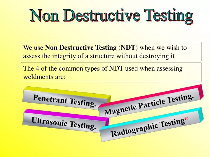
Non Destructive Testing. We use Non Destructive Testing ( NDT ) when we wish to assess the integrity of a structure without destroying it. The 4 of the common types of NDT used when assessing weldments are:. Penetrant Testing. Magnetic Particle Testing. Ultrasonic Testing.

E N D
Non Destructive Testing We use Non Destructive Testing (NDT) when we wish to assess the integrity of a structure without destroying it The 4 of the common types of NDT used when assessing weldments are: Penetrant Testing. Magnetic Particle Testing. Ultrasonic Testing. Radiographic Testing*
Penetrant Testing Procedure First the work must be cleaned thoroughly, then a penetrant is applied for a specified time* Once the contact time has elapsed, the penetrant is removed and a developer is then applied* Any penetrant that has been drawn into a crack by capillary action will be drawn out into the developer* Two types of penetrants are: 1) Colour contrast 2) Fluorescent Penetrant*
Colour Contrast Penetrant Method Apply Penetrant Clean then apply Developer Result*
Advantages and Disadvantages Advantages Disadvantages 1) Low operator skill level 1) Highly clean metal 2) Surface flaws only 2) All materials (Non Porous) 3) Low cost method 3) Extremely messy 4) Simple equipment 4) No permanent record*
Magnetic Particle Testing Procedure First the work must be cleaned and a whitener applied for contrast. A magnetic flux is then applied by permanent magnet, electro magnet, or straight current* A magnetic ink is applied which will concentrate in areas of flux leakage, as those caused by flaws* The weld length must be crossed at 90° by the magnetic field* The types of magnetic media used are:1) Wet ink 2) Dry powder 3) Fluorescent ink*
Magnetic Particle Testing Method Contrast paint Magnet & Ink Result*
Advantages and Disadvantages Disadvantages Advantages 1) Low operator skill level 1) Fe Magnetic metal only 2) De-magnetize after use 2) Sub surface flaws 3) Relatively cheap 3) Can cause arc strikes # 4) Simple equipment 4) No permanent record* # When using the straight current prod technique
Ultrasonic Testing Procedure First the work must be cleaned thoroughly, then a couplant is applied to increase sound transmission* A probe is then applied with the correct angle for the weld preparation and sound waves are transmitted* Any imperfections will rebound the sound waves causing a signal to occur on the cathode ray tube*
Ultrasonic Testing Method Apply Couplant Sound wave Result* CRT display Signal rebounded from Lack of fusion
Advantages and Disadvantages Advantages Disadvantages 1) Can find lack of fusion 1) High operator skill 2) Difficult to interpret 2) Most materials 3) No safety requirements 3) Requires calibration 4) Portable/instant results 4) No permanent record*
Radiographic Testing Procedure A film is placed inside a cassette between lead screens. It is then placed to the rear of the object to be radiographed A radiographic source, is exposed to the work and film for a pre-calculated time* Any imperfections in line with the beam of radiation will be shown on the film after exposure and development* The 2 types of radiation used in industrial radiography: 1) X rays (from Cathode Ray Tube) 2) Gamma rays (from a Radioactive Isotope)*
Radiographic Testing Method Load film Exposure to Radiation Interpret Graph Developed Graph Radioactive source IQI Film cassette Latent image on the film
Advantages and Disadvantages Advantages Disadvantages 1) A permanent record ? 1) High operator skill 2) Difficult interpretation 2) Most materials 3) Assess root pen’ in pipe 3) Lack of sidewall fusion 4) Gamma ray is portable 4) Safety requirements*
Non Destructive Testing New TWI Video “Non Destructive Testing” 30 Minutes
Weld Repairs Weld Repairs: Weld repairs can be divided into two specific areas: 1) Production repairs 2) In service repairs* Production repairs are usually identified by the Welding Inspector, or NDT operator during the process of inspection, or evaluation of reports to the code, or applied standard*
Weld Repairs A typical defect is shown below: * Prior to repair the defect may need to undergo the following: 1) A defect analysis and report 2) An assessment of defect extremity 3) An excavation procedure 4) NDT procedures 5) A welding repair procedure 6) Welder approval to the approved repair procedure 7) Any subsequent treatments procedures i.e. PWHT *
Weld Repairs Plan View of defect with drilled ends * Side View of defect excavation* Completed repair*
Weld Repairs NDT confirmation of successful repair: After the excavation has been filled the weldment should then be undergo a complete retest using NDT to ensure no further defects have been introduced by the repair. NDT may also need to be further applied after any additional post weld heat treatment has been carried out*
Residual Stress & Distortion Residual welding stresses are defined as those stresses that remain inside a material after welding has been carried out Stresses are caused by the heat of welding, which produces local expansion and contraction to take place If a metal was heated & cooled uniformly no stresses would remain, as expansion & contraction would be uniform Welding causes only local heating and cooling conditions to exist, hence some residual stresses to remain in the metal*
Directions of Welding Related Stresses Residual stresses can have very complex patterns in welded constructions. In simple butt welded plates they may be indicated as shown below: Tensile Tensile Compressive *
Directions of Expansion/Contraction We can say that expansion/contraction has three directions. Transverse Plan View of plate Weld Longitudinal End View of plate Shorttransverse
Effects of Expansion/Contraction One effect of welding related stresses is distortion Distortion is the movement of material in one area caused by expansion and contraction, and local elastic/plastic movement that misshapes the component* The various types of distortion produced are caused by the directions and amount of expansion and contractional stresses involved, and the ability of the material to resist the stress without the formation of elastic/plastic strain, or deformation It is this deformation that produces distortion in a product*
Effects of Expansion/Contraction Transverse distortion Longitudinal distortion Angular Distortion*
Effects of Weld Volume on Distortion The volume of weld metal in a joint will also effect the amount of local expansion and contraction Hence the more volume of weld metal then the overall amount of distortion will be higher*
Control of Distortion Many methods are used to control the effects of distortion. Perhaps the best of these is to to pre set the materials to allow distortion to bring it to its final shape. This method is called offsetting, or pre-setting* a) Practical b) Practical c) Impractical*
Control of Distortion Other forms of distortion control stop the movement of material from occurring by using such methods as clamping, jigging, strong backs, and tacking etc* These methods will reduce the distortion, but will also amass the maximum amount of residual stresses to exist* Back-step & balance welding are sequences which may also be used to control the effects of distortion*
Heat Treatments All heat treatments applied to metals are cycles of 3 elements. 1) Heating 2) Soaking 3) Cooling Temp 2 1 3 Time
Heat Treatments Used to make metals soft and ductile Annealing: For steels, the component is heated above its UCT, or upper critical temperature, soaked for 1 hour/25mm of thickness and left in the furnace to cool Produces a coarse grain structure & low toughness* Normalising: Used to make steels tough As for annealing, but the steel is removed from the furnace after soaking to cool in still air Produces a fine grain structure with good toughness*
Heat Treatments Hardening: Used to make some steels harder Used to increase the hardness of some plain carbon & alloy steels. Plain carbon > 0.3% The cycle is the same as previously but the cooling is rapid i.e. Quenched in water, oil, but sometimes air* Tempering: Used after hardening to balance the properties of Toughness & Hardness The temperature range is from 220 – 723 °C The cooling part of the cycle should not be too rapid, but over heating will over temper the steel*
Heat Treatments Used after welding to release residual stresses, caused by welding operations* PWHT: Force/Stress required to induce plastic strain* Stress Y The effect of heat on the position of the yield point* Strain By heating the steel, the yield point is suppressed/reduced relieving residual stresses as plastic strain at a much lower level of stress*
Heat Treatments Pre-Heating: Used mainly on steels to retard the cooling rate of a hardenable steel and reduce the hardening effect (Martensite formation) Is also used to help diffusion of Hydrogen from the HAZ of hardenable steels to avoid hydrogen cracking. Typically < 350 °C Is also used to produce a more uniform rate of cooling, and control distortion, or effects of high contractional strains*
Gas Welding & Cutting Name Pictorial view Uses Fusion welding most metals. Flame temp > 3,200 °C* Neutral Oxidising Bronze Welding* Hard surfacing & fusion & Brazing Aluminium & alloys* Carburising
Oxy/Fuel Gas Cutting A jet of pure oxygen reacts with high temperature iron (>1100 C) to produce Fe3 O4 by exothermic reaction. This dross is then removed by the pressure of the oxygen jet* Different types of fuel gases may be used for the pre-heating flame in oxy fuel gas cutting: i.e. Acetylene. Hydrogen. Propane. Etc* By adding Iron powder to the flame we are able to cut most metals “Iron Powder Injection”* The high intensity of heat and rapid cooling will cause hardening in low alloy, and medium, or high C steels They are thus pre-heated to avoid the hardening effect*
Oxy/Fuel Gas Cutting Slightly rounded top edge caused by too close a nozzle gap The “Kerf” 50mm Flutes
Arc Cutting Processes MMA electrodes are specially produced for cutting and gouging. Oxy/Arc and Arc/Air are arc cutting process that produce lots of fume and arc air produce a high noise level. All these processes require good extraction, and ear protection is vital for arc/air Both oxy arc and arc air use special types of electrodes and gas supplies, which will be described by the course lecturer*
Safety in Welding Operations Safety is the responsibility everyone. As respected officers, it is the duty of all welding inspectors to ensure that safe working practices are strictly followed. Safety in welding can be divided into several areas, some of which are as follows: (Areas to be expanded briefly by the lecturer/presenter) 1) Welding/cutting process safety.* 2) Electrical safety.* 3) Welding fumes & gases. Use & storage of gases.* 4) Safe use of lifting equipment.* 5) Safe use of hand tools and grinding machines.*
Welding Process Safety Careful consideration should be given to safety hazards when using a particular welding process. This may include:* • The hazards of infra red and/or ultra violet light • The hazards of heat, burns and fire • The hazards of toxic and non toxic gases from process, coatings, or purging, and gases stored at high pressure • The hazards of working with high voltages & currents • The hazards of working in confined spaces*
Cutting Process Safety Careful consideration should be given to safety when using gas, or arc cutting systems by:* • Removing any combustible materials from the area • Checking all containers to be cut are fume free and have a Permit to Work • Providing ventilation and extraction where required • Ensuring good gas safety is being practised • Keeping oil and grease away from oxygen • Using ear defenders when arc air cutting
General Safety Safe working with electrical power is mostly common sense. Ensure that insulation is used where required and that cables and connections are in good condition. (Check the duty cycle)* Gases should be stored separately, and cylinders should be secured when used in the vertical position, especially oxygen* Exposure to dangerous welding fumes and gases from electrodes, plating, i.e.ozone,nitrous oxide,phosgene,cadmium, beryllium are to name just a few. Always use extraction/breathing systems. If in any doubt, stop the work*
General Welding Safety From the points that have been covered in the safety lecture, and/or the Video, complete the safety check list exercise in your course text*
The Weldability of Steels “Weldability” is a term used in welding engineering to describe the ease of which a material can be welded by the common welding processes and still retain the properties for which it was designed* If we say that a material has limited weldability, it means that we need to take special measures to ensure that the properties as required are maintained* Most materials are weldable with certain processes. The weldability of steel is mainly dependant on carbon content & alloying, though most steels have a degree of weldability*
The Weldability of Steels for CSWIP 3.1 1) Hydrogen induced HAZ cracking in Low Alloy Steels 2) Hydrogen weld metal cracking in Micro Alloy Steels 3) Solidification cracking in Ferritic steels 4) Lamellar tearing in Ferritic steels 5) Inter-granular corrosion in Stainless Steels*
Classification of Steels Steels are classified into groups as follows:* Plain Carbon Steels:* 1) Low Carbon Steel 0.01 – 0.3% Carbon* 2) Medium Carbon Steel 0.3 – 0.6% Carbon* 3) High Carbon Steel 0.6 – 1.4% Carbon* Plain carbon steels contain only iron & carbon as main alloying elements, traces of Mn Si Al S & P may also be present*
Classification of Steels An Alloy steel is one that contains more than Iron & Carbon as a main alloying elements* Alloy steels are divided into 2 groups:* * Low Alloy Steels< 7% extra alloying elements * High Alloy Steels> 7% extra alloying elements
Basic Atomic Structure of Steels The following basic foundation information on metallurgy will not form any part of your CSWIP examination* A most important function in the metallurgy of steels, is the ability of iron to dissolve carbon in solution* The carbon atom is very much smaller than the iron atom and does not replace it in the atomic structure, but fits between it* Iron atoms Carbon atoms* Iron is an element that can exist in 2 types of cubic structures, depending on the temperature. This is an important feature*
Basic Atomic Structure of Steels At temperatures below Ac/r 1, (LCT) iron exists like this* α Alpha iron This structure occurs below 723 °C and is body centred, or BCC in structure It can only dissolve up to 0.02% Carbon Also known as Ferrite or BCC iron* * Compressed representation could appear like this
Basic Atomic Structure of Steels At temperatures above the Ac/r 3, (UCT) iron exists like this* γ Gamma iron This structure occurs above the UCT in Plain Carbon Steels and is FCC in structure. It can dissolve up 2.06% Carbon Also called Austenite or FCC iron* * Compressed representation could appear like this
Basic Atomic Structure of Steels If steel is heated and then cooled slowly in equilibrium, then exact reverse atomic changes take place* If a steel that contains more than 0.3% Carbon is cooled quickly, then the carbon does not have time to diffuse out of solution, hence trapping the carbon in the BCC form of iron. This now distorts the cube to an irregular cube, or tetragon* This supersaturated solution is called Martensite and is the hardest structure that can be produced in steels*