Download

1 / 26
300 likes | 642 Views
Traveling Wave. Transient Overvoltages. 1.Introduction. Transient Phenomenon : Aperiodic function of time Short duration

E N D
Traveling Wave Transient Overvoltages
1.Introduction • Transient Phenomenon : • Aperiodic function of time • Short duration • Example :Voltage & Current Surge :(The current surge are made up of charging or discharging capacitive currents that introduced by the change in voltages across the shunt capacitances of the transmission system) • Lightning Surge • Switching Surge
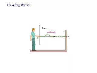
2.Traveling Wave • Disturbance represented by closing or opening the switch S. • If Switch S closed, the line suddenly connected to the source. • The whole line is not energized instantaneously. • Processed : • When Switch S closed • The first capacitor becomes charged immediately • Because of the first series inductor (acts as open circuit), the second capacitor is delayed • This gradual buildup of voltage over the line conductor can be regarded as a voltage wave is traveling from one end to the other end
vf=v1(x-t) vb=v2(x+t) = 1/(LC) v(x,t)=vf + vb vf=Zcif vb=Zcib Zc=(L/C)½ If=vf/Zc Ib=vb/Zc I(x,t)=If + Ib I(x,t)=(C/L) ½[v1(x-t) -v2(x+t)] Voltage & Current Function
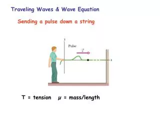
2.1 Velocity of Surge Propagation • In the air = 300 000 km/s • = 1/(LC) m/s • Inductance single conductor Overhead Line (assuming zero ground resistivity) :L=2 x 10⁻⁷ ln (2h/r) H/mC=1/[18 x 109 ln(2h/r)] F/m • In the cable : = 1/(LC) = 3 x 10⁸ K m/sK=dielectric constant (2.5 to 4.0)
2.2 Surge Power Input & Energy Storage • P=vi Watt • Ws= ½ Cv2 ; Wm= ½ Li2 • W=Ws+Wm = 2 Ws =2 Wm = Cv2 = Li2 • P=W = Li2 /(LC) = i2 Zc = v2 / Zc
3. Effects of Line Termination • Assuming vf, if,vb and ib are the instantaneous voltage and current. Hence the instantaneous voltage and current at the point discontinuity are : • v(x,t)=vf + vb and I(x,t)=If + Ib • I=vf/Zc - vb/Zc and iZc=vf – vb • v + iZc= 2vf so v=2vf=iZc • vf = ½ (v+iZc) and vb = ½ (v+iZc) or vb= vf-iZc
Line is terminated with its characteristic impedance : • Z=Zc • =0, no reflection (infinitely long) • Z>Zc • vb is positive • Ib is negative • Reflected surges increased voltage and reduced current • Z<Zc • vb is negative • Ib is positive • Reflected surges reduced voltage and increased current • Zs and ZR are defined as the sending-end and receiving end.
3.3 Open-Circuit Line Termination • Boundary condition for current i=0 • Therefore if=-ib • Vb=Zcib=Zif=vf • Thus total voltage at the receiving endv=vf+vb=2vf • Voltage at the open end is twice the forward voltage wave
3.4 Short Circuit Line Termination • Boundary condition for current v=0 • Therefore vf=-vb • If=vf/Zc=-(vb/Zc)=ib • Thus total voltage at the receiving endv=if+ib=2if • Current at the open end is twice the forward current wave
5. Junction of Several Line Example: