Download
1 / 32
320 likes | 436 Views
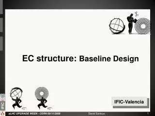
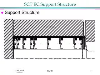
EC Structure Review. ?. ?. ?. ?. ?. ?. IFIC-Valencia. Presented at Nikheff Ws 2008. EARLY MODEL: Mass reduction target. - Petals supported by a wheel - Hub and rim of the wheel sustained by a set of radial rods. Presented at Nikheff Ws 2008.

E N D
EC Structure Review ? ? ? ? ? ? IFIC-Valencia
Presented at Nikheff Ws 2008 EARLY MODEL: Massreduction target - Petals supported by a wheel - Hub and rim of the wheel sustained by a set of radial rods
Presented at Nikheff Ws 2008 Overlap in Φ with upper/lower petals Two Control Cads per petal on same side CONTROL CARD LOCATION FIXED: - Control Card on the side. No space left at the top (outer radius) - Control Card at the bottom difficulties services connections. - “T-shape” difficulties Control Card cooled down with the return pipe
Presented at LBL Mech-Ws 2009 • ”End insertion”-like concept is complicated for petals: • - Control cards on the side “only 1 rail?” • - There is no mov. constrain in z (No disk) • - Rings separate petals in z even more (Rods Ø) • - Build accuracy requirements: • r-φ=50um r=200um z=500um Stiff enough? At least Inner Cylinder (Cone shaped) required
Presented at LBL Mech-Ws 2009 This would improve considerably the stiffness but…
Presented at LBL Mech-Ws 2009 What about services?? Risky: multiple obstacles with NO “end-insertion”-like concept
Services: Presented by Neal D. Hartman (Jan.2009) Characteristic, Repeated 1/16 Arc Segment EC Service Module Connection Space EC Pix SB PP1 PCB’s Poly Moderator Supplement
16 Service channels for EndCap Characteristic, Repeated 1/16 Arc Segment EC Pix SB From Ian Wilmut concept applied to petals
16 Service channels for EndCap A single “rail” makes end-insertion easier until the very end of the assembly process… Single guide pin This gap can be reduced depending on the piping and cabling connectors.
Services: Presented by Christophe Bault (Feb.2009) R=974 R=1007
CF Inner Cylinder Apertures on Outer cylinder to permit services exit 8 support bars constrain disks Inner cylinder with 4 different diameters to constrain disks and sustain petals Master disk supports entire structure
CFRP-KOREX Disks 1.- Master Disk + Support bars + Inner cylinder 2.- Disks are assembled into the structure.
(4/16) Rows of Petals: Services and Testing 40 petals from 160 (25%)
Services & cabling Servicesestimationincludes: • Opto fibersx18 • HV cablingx18 • LV cablingx2 • Inlet and Outletcapillaries • DCS x18 • Al servicechannel Capillaries
Electrical & Cooling Services Interface Electrical Connectors on top to improve accessibility. Also located at the center to optimize the area for the Control Card on the side. The aim is to reduce the petal width as much as possible.
Services Connections 2D-Layout: conflictive area at rails CONNECTORS NEED TO BE DEFINED: AT MANIFOLDING PIPES SHOULD HAVE THE SAME IMPEDANCE 1.4m
Accessible area after services 40 petals from 160 (25%) +12 (32,5%) +12 (40%) 1.4m
ENDCAP Envelope: Substructure #1 Support Frames Support Beam Inner Cylinder Disks supports
ENDCAP Envelope: Substructure #2 Rings Services Channels
Petal Envelope Dimensions Only element to determine Inner diameter of ring >>>>> 12mm GAP??? >>>>> 7mm GAP??? >>>>>
9 Rings for Services; Weights and Clearances TOTAL nº RINGS = 9 x 2 = 18 (TOP+BOT) ≈4.4 Kg → Openings ≈4.4 Kg → ≈4.4 Kg → ← ≈74mm ← ≈242mm ≈4.0 Kg → ≈4.0 Kg → ≈4.0 Kg → ← ≈88mm ← ≈88mm ≈3.1Kg → ≈3.1Kg → ← ≈88mm ← ≈74mm ≈2.2 Kg → ← ≈74mm TOTAL SERVICES = 33.6 x 2 = 67.2Kg (TOP + BOT)
2 Models considered… Real model reinf. inserts Real model 12mm GAP?-> 12mm GAP?-> Real model with openings Equivalent model Equivalent model 12mm GAP?
Results and Conclusions… For the real model without inserts, the areas where the load is distributed provide about 80% of the deflection because there is not enough rigidity at those areas. This is why the equivalent model is done to avoid the previous situation. The model with Inserts shows the best data it is possible to get, the load is sheared between all nodes in contact with the inserts areas. To achieve a deformation under 5mm is not impossible, but some safety factor must be also considered and it is difficult with current estimations to understand if already there is a safety factor included at the load or not. Results: Outer diameter: 1.007mm Inner diameter: 0.979 mm 12mm GAP Deformation results: Units in mm Material Properties Carbon Fiber: XN50-A Matrix: RS-3 Honeycomb: KOREX 5/32-2.4 Results: Outer diameter: 1.007mm Inner diameter: 0.974mm 7mm GAP
Next Future… The structure frames are the only element which affects to the dimension for the inner ring diameter. Rings are part of the full structure and if frames could pass through the rings by small openings -> Next idea to develop! …This concept would make possible to reduce rings width allowing bigger clearances to extract petals. Opening for services Opening for frames Service Ring