Download
1 / 56
600 likes | 885 Views
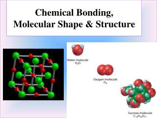
Chapter 3. MOLECULAR SHAPE AND STRUCTURE. THE VSEPR MODEL. 3.1 The Basic VSEPR Model 3.2 Molecules with Lone Pairs on the Central Atom 3.3 Polar Molecules. VALENCE-BOND THEORY. 3.4 Sigma and Pi Bonds 3.5 Electron Promotion and the Hybridization of Orbitals

E N D
Chapter 3. MOLECULAR SHAPE AND STRUCTURE THE VSEPR MODEL 3.1 The Basic VSEPR Model 3.2 Molecules with Lone Pairs on the Central Atom 3.3 Polar Molecules VALENCE-BOND THEORY 3.4 Sigma and Pi Bonds 3.5 Electron Promotion and the Hybridization of Orbitals 3.6 Other Common Types of Hybridization 3.7 Characteristics of Multiple Bonds 2012 General Chemistry I
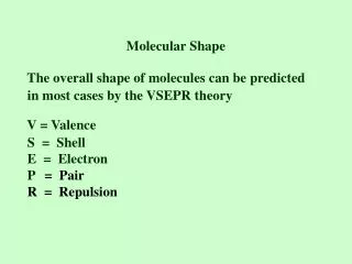
THE VSEPR MODEL (Sections 3.1-3.3) 3.1 The Basic VSEPR Model – Lewis structure: showing the linkages between atoms and the presence of lone pairs, but not the 3D arrangement of atoms • Valence-shell electron-pair repulsion model (VSEPR model, first devized by Sidgwick and Powell, later modified by Gillespie and Nyholm) is based on Lewis structures. Molecular shapes are predicted • by use of several rules that account for bond angles.
Generic “VSEPR formula”, AXnEm - A = central atom; Xn = n atoms bonded to central atom Em = m lone pairs on central atom E.g. BF3 (AX3), SO2 (AX2E), SO32- (AX3E), CH4 (AX4), PCl5 (AX5) • Rule 1. Regions of high electron concentration (bonds and lone pairs on the central atom) repel one another and, to minimize their repulsions, these regions move as far apart as possible while • maintaining the same distance from the central • atom. This gives rise to the basic geometries, which are related to the total number (Xn + En) of electron pairs around the central atom (next slide).
Rule 2. There is no distinction between single and multiple bonds: a multiple bond is treated as a single region of high electron concentration. E.g.
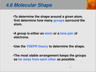
3.2 Molecules with Lone Pairs on the Central Atom • Rule 3. All regions of high electron density, lone pairs and bonds, • are included in a description of the electronic arrangement, but • only the positions of atoms are considered when identifying the • shape of a molecule. • E.g. Angular (bent or V-shape) Trigonal pyramidal
Rule 4 The strength of repulsions are in the order • lone pair-lone pair > lone pair-atom > atom-atom. trigonal pyramidal - AX3E type more stable - AX4E type seesaw shaped axial equatorial - AX3E2 type - AX4E2 type T-shaped square planar
Predicting the molecular shape of SF4 Step 1 Draw the Lewis structure. Step 2 Assign the electron arrangement around the central atom. Step 3 Identify the molecular shape. AX4E. Step 4 Allow for distortions. (Bent) seesaw shape
3.3 Polar Molecules • Polar molecule: a molecule with a nonzero dipole moment. • A diatomic molecule is polar if its bond is polar (if the electronegativity • difference between the two atoms > 0.3) - see Chapter 2.12. E.g. HCl is a polar molecule (dipole moment of 1.1 D). H2 is a nonpolar molecule (zero dipole moment). - A polyatomic molecule is polar if it has polar bonds arranged in space in such a way that the dipole moments associated with the bonds do not cancel. See Table 3.1 for dipole moments of selected molecules.
polar nonpolar polar nonpolar
Molecular geometries giving non-polar or polar molecules: AX2 – AX3E2 (Fig. 3.7)
Molecular geometries giving non-polar or polar molecules: AX4 – AX6 (Fig. 3.7)
VALENCE-BOND (VB)THEORY (Sections 3.4-3.7) • The VB theory is based on the Lewis model: each bonding electron pair is localized between two bonded atoms. • It is a localized electron model, devized originally by Heitler and London, and later modified by Pauling, Slater and others.
3.4 Sigma (s) and Pi (p) Bonds • Thes-bond is formed by ‘head-on’ overlap: there is no nodal surface containing the interatomic (bond) axis. - It is cylindrical or “sausage” shaped. E.g. H2, s(1s, 1s) HF, s(1s, 2pz) See next slide N2, s(2pz, 2pz)
The p-bond is formed by ‘sideways’ overlap: there is a nodal plane containing the interatomic (bond) axis. • It is composed of two cylindrical shapes (lobes), one above • and the other below the nodal plane. N2 one s-bond with two perpendicular p-bonds - In General,single bond (one s-bond), double bond (one s- and one p-bond) triple bond (one s- and two p-bonds)
3.5 Electron Promotion and the Hybridization of Orbitals all C-H bonds equivalent ? • Electron promotion: electron relocated to a higher-energy orbital promotion hybridization
Hybrid orbitals: produced by hybridizing orbitals of a central atom C [He]2s12px12py12pz1 4 sp3 hybrids h1 = s + px + py + pz h3 = s - px + py - pz h2 = s - px - py + pz h4 = s + px - py - pz each C-H bond sp3 hybrid orbital
Examples of sp3 hybrid orbitals in bonding - Ethane, C2H6 Each C atom uses sp3 hybrid orbitals. The C-C bond is formed as s(C2sp3, C2sp3). Each C-H bond is formed as s(C2sp3, H1s). - Ammonia, NH3 Four sp3 hybrid orbitals; one occupied by a lone pair, and the other three forming N-H s-bonds
3.6 Other Common Types of Hybridization • sp2 hybrid orbitals in BF3 • sp hybrid orbitalsin CO2
- sp3d2 hybrid orbitals in SF6 and XeF4 - sp3d hybrid orbitals in PCl5
3.7 Characteristics of Multiple Bonds - Ethene, CH2=CH2 C-C s bond, s(C2sp2, C2sp2) C-C p bond, p(C2p, C2p) each C-H bond formed as s(C2sp2, H1s)
- Benzene, C6H6 C-C s bond, s(C2sp2, C2sp2) C-C p bond, p(C2p, C2p) Each C-H bond formed as s(C2sp2, H1s) - Ethyne (acetylene), C2H2 C-C s bond, s(C2sp, C2sp) Two C-C p bond, p(C2px, C2px), p(C2py, C2py) Each C-H bond formed as s(C2sp, H1s)
Chapter 3. MOLECULAR SHAPE AND STRUCTURE MOLECULAR ORBITAL THEORY 3.8 The Limitations of Lewis’s Theory 3.9 Molecular Orbitals 3.10 Electron Configurations of Diatomic Molecules 3.11 Bonding in Heteronuclear Diatomic Molecules 3.12 Orbitals in Polyatomic Molecules 2012 General Chemistry I
MOLECULAR ORBITAL THEORY(Sections 3.8-3.12) 3.8 The Limitations of Lewis’s Theory • Valence Bond (VB) theory deficiencies - Cannot explain paramagnetism of O2 (existence of unpaired electrons) - Difficulty treating electron-deficient compounds such as B2H6 - No simple explanation for spectroscopic properties of compounds • Molecular Orbital (MO) theory advantages - Addresses all of the above shortcomings of VB theory - Provides a deeper understanding of electron-pair bonds - Accounts for the structure and properties of metals and semiconductors - Universally used in calculations of molecular structures
3.9 Molecular Orbitals • Molecular orbitals (MOs) contain the valence electrons in molecules: they are delocalized over the whole molecule. - In VB theory, bonding electrons are localized on atoms or between pairs of atoms. - n molecular orbitals must be constructed from n atomic orbitals: • MOs are formed by linear combination of atomic orbitals • (LCAO-MO): - Bonding orbital (constructive interference) y = yA1s + yB1s → overall lowering of energy - Antibonding orbital (destructive interference) y = yA1s - yB1s → overall raising of energy
Molecular orbital energy-level diagram MO energy-level diagrams are an integral part of MO theory: they give the following information. 1. Relative energies of original AOs and resulting MOs 2. Orbital location of electrons and electron spin (using arrows) H2 - In H2, two 1s-orbitals merge to form the bonding orbital s1s and the antibonding orbital s1s*
3.10 Electron Configurations of Diatomic Molecules Constructing MOs (by combining AOs) must follow a number of rules,the first three of which are similar to those of the ‘Building-up Principle’ for constructing atomic electron configuration: 1. Electrons are accommodated in the lowest-energy MO, then in orbitals of increasingly higher energy. 2. According to the Pauli exclusion principle, each MO can accommodate up to two electrons. If two electrons are present in one orbital, they must be paired. 3. If more than one MO of the same energy is available, the electrons enter them singly and adopt parallel spins (Hund’s rule).
4. Only atomic orbitals of the same symmetry along the bond axis can be combined. 5. Atomic orbitals of the same or similar energy interact more strongly than those with very different energies. Low energy AOs contribute more to bonding MOs; high energy AOs contribute more to antibonding MOs.
Homonuclear diatomic molecules of Period 2 elements (Li2 – F2) General Features • Two 2s atomic orbitals (one on each atom) overlap to form • two s orbitals: one bonding (s2s-orbital) and the other antibonding • (s2s*-orbital). - Six 2p atomic orbitals (three on each atom) overlap to form six MOs: two 2pz orbitals to form s bonding and antibonding (s2p, s2p*) MOs, and four 2px, 2py orbitals to form two p2p and two p2p*MOs. See next slide.
For O2 and F2 Four 2px, 2py AOs form two p2p and two p2p* MOs Two 2pz AOs form bonding s2pand antibonding s2p* MOs Two 2s AOs form one bonding (s2s) MO and one antibonding (s2s*) MO
- For O2 and F2, the energy levels of 2s and 2p are well-separated. from Shriver
- From Li2 to N2, the energy levels of 2s and 2p are close, and thus the 2s orbital also participates in forming s2p orbitals. from Shriver
MO theory account of bonding in N2 - In N2, each atom supplies five valence electrons. A total of ten electrons fill the MOs. LUMO The ground configuration is, b = ½(8-2) = 3 HOMO • Bond order (b): net number of bonds
MO theory account of bonding in O2 - In O2, each atom supplies six valence electrons. A total of twelve electrons fill the MOs. The ground configuration is, LUMO HOMO b = ½(8-4) = 2 accounts for paramagnetism of O2
3.11 Bonding in Heteronuclear Diatomic Molecules • A diatomic molecule built from atoms of two different elements • is polar, with the electrons shared unequally by the two atoms. - In a nonpolar covalent bond, cA2 = cB2 - In an ionic bond, the coefficient belonging to one ion is zero. - In a polar covalent bond, the AO belonging to the more electronegative atom has the lower energy, and so it makes the larger contribution to the lowest energy (bonding) MO. - Conversely, the contribution to the highest- energy (most antibonding) orbital is greater for the higher-energy AO, which belongs to the less electronegative atom.
- For HF, electronegativity of F (4.0), H (2.2) - For EO (E = C or N), mainly H1s-orbital → partial (+) charge on H mainly F2pz-orbital → partial (–) charge on F
3.12 Orbitals in Polyatomic Molecules - The MOs spread over all atoms in the molecule. Experimentally studied by using ultraviolet and visible spectroscopy. • Water, H2O - A water molecule with six atomic orbitals (one O2s, three O2p, and two H1s) antibonding orbitals O2px nonbonding orbitals H1s-O2py-H1s bonding orbitals H1s-(O2s,2pz)-H1s