Download
1 / 40
400 likes | 606 Views
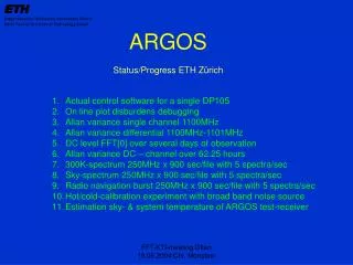
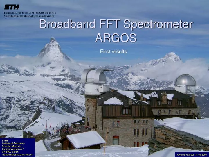
Broadband FFT Spectrometer ARGOS. First results. ETHZ Institute of Astronomy Christian Monstein Scheuchzerstrasse 7 CH-8092 Zürich monstein@astro.phys.ethz.ch. ARGOS-GG.ppt, 14.04.2005. Content. Specifications, block diagrams FPGA, VHDL, resource table

E N D
Broadband FFT Spectrometer ARGOS First results ETHZ Institute of Astronomy Christian Monstein Scheuchzerstrasse 7 CH-8092 Zürich monstein@astro.phys.ethz.ch ARGOS-GG.ppt, 14.04.2005
Content • Specifications, block diagrams • FPGA, VHDL, resource table • Schedule, cost, additional information • KOSMA block diagram, measurement methods • Gornergrat impressions • Measurements in the laboratory • Spectrum results • Software, GUI • RF-overview Gornergrat 3100m, Bleien 420m and Diavolezza 3000m • Conclusions FPGA = Field Programmable Gata Array VHDL = Very High Speed Integrated Circuit Description Language KOSMA = Kölner Observatorium für SubMillimeter Astronomie GUI = Graphical User Interface RF = Radio Frequency
Specifications PCI = Peripheral Component Interconnect (local bus standard) AD = Analog Digital Converter
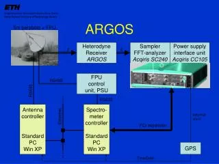
Block diagram AC240 Opt. DRAM Opt. SRAM Digital processing Unit FPGA Xilinx Virtex-2 pro XC2VP70 Additional digital l/O from/to telescope Analog output 2 x 128 bits Δt=0.5nsec Preamp 1GHz Demux 1 8 bits x 16 ADC 1 1Gs/s 8 bit Ch1 Cross Point Switch Preamp 1GHz Demux 2 8 bits x 16 ADC 2 1Gs/s 8 bit Ch2 Trigger PCI Bus Time Base Controller PCI Interface Ext trigger Ext clock
Block diagram AC240 1 Gs/s complex 16 k FFT Pipeline complex input complex output Post Processing Unit even Σ 2 Gs/s real Redundant data j odd 1 Gs/s complex 1 Gs/s complex 2 x 1 Gs/s real
32K FFT with 2Gs/sec throughput 125MHz 125MHz
VHDL design with MENTOR tool Design Entry : HDL Desinger 2004.1a Simulation : ModelSim 5.8c Synthese : Precision RTL 2004.a1 Place & Route: Xilinx ISE 6.2i
Utilization FPGA resources • No use of internal Power-PC (gray area) foreseen • Purple = input structure and programmable window • Yellow = pipeline #1, green = pipeline #2 • Violet = output structure • horizontal structure = Block-RAM and multipliers
Xilinx FPGA Virtex II XC2VP70-6 resources • Slices 29‘247 88.4% • Flip Flops 38‘272 57.2% • Block-RAM 300 91.5% • Multiplier 192 58.5% • fmax 138 MHz (required: 125 MHz)
Schedule • Planned In fact • Start of KTI-project: 2003-11-01 2004-11-01 • Decision system architecture: 2004-03-18 2004-03-18 • Preliminary tests of 1st implementation: 2004-08-30 2004-09-30 • System ready for Radio Astronomy: 2004-12-20 2005-03-18 • Scientific analysis, fist results: 2005-03-07 2005-04-05 • End of project, closing report to KTI: 2005-04-02 2005-05-31
Costs Acqiris sampler 2Gs/s AC240 20’000 Euro Option FFT (Bitfile) 4’000 Euro PCI-interface IC414 1’400 Euro Blanking panel XB200 100 Euro 3-slot crate CC103 2’500 Euro Driver (Win/Linux) free of charge 0 Euro Standard-PC with one free PCI-slot 2’000 Euro FFT – spectrometer 30’000 Euro Some statistics to remember….: 1,8 Euro per FFT-channel or 33KHz bandwidth for every single Euro Actual prices to be negotiated with Acqiris!
Additional information • Project management & tests: ETH Zurich: • Prof. A. O. Benz • - Chr. Monstein • - Hansueli Meyer • Algorithms: FHS (Fachhochschule Solothurn): • - Bruno Stuber • VHDL design: ZMA (Zentrum für Mikroelektronik Aargau): • Prof. K. Schenk • D. Zardet • Industry: Acqiris company Geneva: • - Dr. V. Hungerbühler et. al. Additional information: http://www.astro.phys.ethz.ch/instrument/argos/argos_nf.html http://www.acqiris.com
Block diagram KOSMA AOS LRS 1000MHz/1450 KOSMA DSP KOSMA control Positioning unit AOS MRS 300MHz/1800 Receivers 200…900GHz AOS HRS 59MHz/2048 Local oscillator unit IF unit ETH-FFT 1GHz/16384 Digital I/O IF = 350MHz±150MHz -Data ready -Wobbler control PC Win XP Argos,FTP, VNC Intranet To Internet Laptop LINUX IDL PC Win XP Office, VNC Printers
KOSMA Control room Ilona Miller
Allan time hot noise source Data: 3.6 GByte in total, (extraction of Saturday, 02.04.2005. Used for analysis 08:15 - 21:00) FPGA: 52.8°C ±0.2K Place : Library SEC Range: 50mVpp [sec]
Receiver temperature 230GHz Birdies < 200MHz and > 500MHz are out of KOSMA-IF (red shaded area)!
DR21K 12CO 2→1 Some single spectra 15sec each ↑ = source - reference ↓ = reference - source
DR21K 12CO 2→1 Ti = 90sec BW = 61KHz 230.537994GHz Ti = 179sec BW = 47KHz
DR21K 12CO 3→2 Channel width 60KHz Ti = 200sec Channel width 560KHz Ti = 400sec
ORION A 12CO 2→1 Channel width 240KHz Ti = 10sec Channel width 560KHz Ti = 20sec
AFGL 2591 12CO 3→2 Channel width 240KHz Ti = 160sec Channel width 560KHz Ti = 320sec
IRC 10216 12CO 2→1 Observation 3h SNR with BW=240KHz, Ti=3420sec Ta with BW=560KHz, Ti=5700sec
Dual beam switched mode Tamax≈ 1Kelvin
Frequency switching 12CO 2→1 Fo = 230’537.994MHz ± 10.5MHz
Ozone in the atmosphere AOS saturated
ARGOS on-line graphics Sky noise Zero noise The ADC-range has to be adjusted such that peak amplitudes don’t strike maximum values but, the ADC should be set to maximum gain while observing a hot load. Comb noise
Time- & frequency domain Gornergrat 3100m asl 10sec base band dc-1GHz 30sec IF (230GHz - RX)
Time- & frequency domain duringVP Diavolezza 3000m asl Radar pulse 1028...1030MHz using an L-band down converter Echo of ionosphere sonder 16…30Mhz while doing Jupiter/Io observations.