Download
1 / 42
1.09k likes | 2.58k Views
“Real-time Clock”. Texas Instruments University Programme Teaching Materials. Real-time Clock. Introduction. Portable devices such as mobile phones and PDAs display time and date Typically, time and date functions are controlled by a real-time clock, which runs off its own battery

E N D
“Real-time Clock” Texas Instruments University Programme Teaching Materials
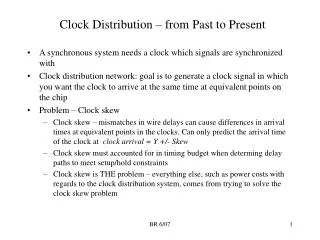
Introduction • Portable devices such as mobile phones and PDAs display time and date • Typically, time and date functions are controlled by a real-time clock, which runs off its own battery • The real-time clock can also be used to control other functions such as alarms, power management and event scheduling.
Objectives • To configure the Real-time Clock (RTC) on the TMS320C5505 USB Stick • To introduce the Texas Instruments Chip Support Library (CSL) • To use the RTC to produce interrupts once every 1 second • To use the RTC to control Phase Locked Loop (PLL) to control the operating frequency and the power taken.
TMS320C5505 Real-Time Clock
RTC Clock Signals • The RTC Clock signal can be used to drive the System Clock (SYSCLK) • The output from the RTC is available on the RTC_CLKOUT pin of the TMS320C5505 USB Stick.
RTC Frequency • The Real Time Clock runs at 32768 Hz • Slow enough to save battery life • Fast enough to give resolution of 1ms per ‘tick’ • A 32768 Hz crystal is a low cost item – it is widely used in digital watches.
RTC Time and Date Functionality • The real-time clock provides the following values for time and date operations: • Year • Month • Day • Hour • Minute • Second • Millisecond.
RTC Alarm Functionality • The alarm functions like a standard alarm clock • When a certain time is reached, the alarm becomes active.
RTC Update Register • When new values of time, date or alarm are written, the new values do not take effect until the TIMEUPT and/or ALARMUPDT bits are written • (Register RTCUPDATE 1901h).
Interrupt Enable Register • In order to turn on RTC interrupts, the RTC interrupt must be enabled. (Register RTCINTEN 1900h).
Interrupt Flag Register • Every time one of the RTC interrupt occurs, a flag needs to be cleared (Register RTCINTFL 1920h).
RTC Power Management • Sets up wake up and controls the clock output on RTC_CLKOUT pin. (Register RTCPMGT 1930h).
RTC Compensation • The 32768 Hz crystal frequency varies with temperature • To keep the time and date accurate, compensation can be applied. (Register RTCDRIFT 1928h).
Using the Chip Support Library (CSL) • Some good news! • Most the functions required to implement a RTC in software are already provided by the Chip Support Library (CSL) • This saves a great deal of work, particularly when implementing interrupts • It can be downloaded from www.ti.com
CSL Example Code • The code for this application has been based on the CSL example code csl_rtc_example.c
CSL RTC Data Structures • csl_rtc.h provides data structures for time and date.
Interrupt Requests (IRQs) • The IRQ function prototypes are provided in csl_intc.h
RTC to Control System Power
LED Flash on Mobile Phone • A typical example of a RTC being used to control system power on a mobile phone might be: • When the phone is not in use, it is put to “sleep” • When 1 second in RTC has expired, the LED flashes and the processor wakes up • If there is an incoming call, the PLL is set to maximum speed • When the call is complete, the processor goes back to sleep.
Interrupt Service Routine (ISR) • The C code uses the special keyword “interrupt”.
Bad Programming Practice • Interrupts should be kept short so they run fast • Do not use “printf” or any other slow function in an interrupt.
Installing the Application • Copy the code given in Application 19 Real Time Clock to the workspace • Follow the steps previously given in Chapter 1 to set up the new project.
TMS320C5505 USB Stick Setup USB to PC Microphone Headphones
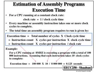
How the Program Works • The program uses the RTC to control the PLL frequency and power dissipation • The RTC produces a periodic interrupt once every second • After 10 seconds the PLL changes from 40 MHz to 2 MHz (Low power) • After 60 seconds an alarm occurs. The the PLL changes to 100 MHz. (Full power. Maximum speed) • After 120 seconds a second alarm occurs which changes the PLL to 12 MHz (Lower power).
Monitoring RTC CLKOUT • The 32768 Hz RTCCLK is available on the RTC_CLKOUT pin of the TMS320C5505 USB Stick • It can be measured using a digital frequency meter.
Setup New Time and Date • In real_time_clock.c, the date, time and alarm times are: • Date: 2010 May 25 • Time: 12 hours: 12 minutes: 12 seconds. • Alarm: 12 hours : 13 minutes : 12 seconds • Change these values to the actual date and time you are running your experiment.
Questions • If you change the time, date or alarm time, what extra register needs to be written to cause the values to change? • How accurate does the RTC clock have to be? Ideally the time and date should be accurate within 30 seconds per month or the customers will complain!
References • TMS320VC5505 DSP System User’s Guide. SPRUFP0. • TMS320VC5505/5504 DSP Real-Time Clock (RTC) User’s Guide. SPRUFO7. • TMS320C55xx Chip Support Library API Reference Guide. SPRU433.