Download
1 / 23
230 likes | 418 Views
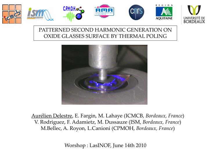
PATTERNED SECOND HARMONIC GENERATION ON OXIDE GLASSES SURFACE BY THERMAL POLING. Aurélien Delestre , E. Fargin, M. Lahaye (ICMCB, Bordeaux, France ) V. Rodriguez, F. Adamietz, M. Dussauze (ISM, Bordeaux, France ) M.Bellec, A. Royon, L.Canioni (CPMOH, Bordeaux, France ).

E N D
PATTERNED SECOND HARMONIC GENERATION ON OXIDE GLASSES SURFACE BY THERMAL POLING Aurélien Delestre, E. Fargin, M. Lahaye (ICMCB, Bordeaux, France) V. Rodriguez, F. Adamietz, M. Dussauze (ISM, Bordeaux, France) M.Bellec, A. Royon, L.Canioni (CPMOH, Bordeaux, France) Worshop : LasINOF, June 14th 2010
Outline I / Thermal poling and Second Harmonic Generation (SHG) II / Silver injection by thermal poling and SHG - Samples elaboration and preparation for silver injection - poling voltage and SHG efficiency - Results and interpretation III / Efficient structuring of SHG - Laser ablation, poling - µSHG patterning measurements - Results and interpretation 02 /15
230°C Anode Cathode G U = 1kV A - Eint - i ~ 0.5 mA - - - - - - - - - - - - - - - - - - - - Thermal poling for Internal field engraving Glasses are centro-symmetric materials(2)=0 Mobile cations can migrate from anode to cathode Eint Na+ cations depletion zone creation (L=3-15 µm) Negatively charged depletion zone Eint Embedded internal field induces Second Harmonic Generation in Glasses 03 / 15
Metallic silver film Glass ~ 5 mm Glass samples elaboration + silver injection Composition : sodium and niobiumborophosphate glasses (BPN42) (1-x)[0,95NaPO3+0,05Na2B4O7]+xNb2O5 x = 0,42 Silver layer deposition on the glass surface Silver injection by poling : - departure of sodium ions - injection of silver ions Thermal Poling induces Zone outside the anode Zone under the anode SHG modified ? Poled surface after poling Na+ and Ag+ : Comparable diffusion coefficients in oxide glasses Structuration of silver electrode SHG structuration Why silver ? 04 / 15 *Référence : M. Dussauze Optics Express, Vol. 13, Issue 11, pp. 4064-4069
c(2) values deduced from Maker Fringes simulations Thermal poling 230 °C, t = 1 h, U ~ 1 kV, i0 = 0.5 mA (sample thickness 1 mm) Observation :Efficient poling leads to (2)comparable to the reference Why poling is efficient? Why poling can be inefficient? 05 / 15
Reference Without Ag Poled zone Anode Cathode Quantitative X-ray analysis on the reference Na, Nb, P atomic concentration profiles Poled zone Sodium depletion zone: 3 µm thickness Space charge zone identical to SHG efficient zone 06 / 15 *Reference : M. Dussauze Optics Express, Vol. 13, Issue 11, pp. 4064-4069
Atomic concentration profiles under the anode 20 Na depletion zone Ag injection zone 18 16 efficient SHG zone 14 12 % Atomic 10 8 6 Na Ag 4 P Nb 2 0 0 2 4 6 8 10 12 14 16 2.9 Depth under the anode surface (µm) Quantitative X-ray analysis Efficient poling withAg Cations migrations : - Na+ ions depletion (6 µm) - Ag+ ions penetration (6 µm) SHG profile correlated to total cations depletion - between 2.9 µm and 6 µm Ag substitutes to Na - the nonlinear zone producing SHG is located between 0 to 2.9 µm under the surface 07 / 15
No SHG Quantitative X-ray analysis Inefficient poling with Ag Atomic concentration profiles 16 Cations migration : déplétion zone 14 • Na+ depletion ( 2 µm) • Ag+ injection ( 2 µm) 12 10 % Atomic 8 Ag+ injection compensates Na+depletion 6 Na Ag 4 P Nb 2 0 0 2 4 6 8 10 12 Depth under the anode surface (µm) No space charge zone creation Poling voltage ~1 kV is the minimum to develop efficient poling 08 / 15 *reference : E. Fargin Advanced Materials Research Vols. 39-40 (2008) pp 237-242
Influence of voltage on poling efficiency First polings mistake : special attention on the current Now big care on the voltage !!! Thermal poling 230 °C, t = 1 h, U = different voltage, i0 < 0.6 mA (sample thickness 500µm) SHG efficiency is linked with poling tension 09 / 15
Laser fs IR Laser fs IR Laser fs IR Laser fs IR Laser fs IR Laser fs IR AOM AOM AOM AOM AOM AOM Ablated line 100µm SHG architecture BPN42 + Ag thin film deposition Laser Ablation of silver lines (Length = 3 mm, width = 2 µm) Thermal poling 230 °C, t = 1 h, U = 1 kV, i0 < 0.6 mA Ag thin film laser Yb : Wavelength = 1030 nm pulse duration= 470 fs Repetition rate = 10 MHz Mean power = 6 W Surface profile image of ablated lines Image of ablated lines (optical microscopy) 10 / 15
-30 -20 Ag Ablated Poled lines -10 X (µm) 0 10 20 Ag Non ablated poled zone 30 20 -40 -20 0 40 Y (µm) µGSH allows different fields orientations Different components in µSHG Analysis Ablated lines 2ω (polarization of reflected SHG field) ω (polarization of incident beam field) Exemple : YXX 11/ 15
14 12 Flight intensity xxx(2) 0 10 Intensité (u.a.) 8 6 4 2 0 -500 0 500 1000 Wavenumber (cm-1) Nombre d’onde (cm-1) Ablated zone : 600 3D mapping: 500 Intensité (u.a.) 400 300 Z=0 Z=2 Z=1 Z=4 Z=3 200 3 µm under the surface Surface 100 0 -500 0 500 1000 Nombre d’onde (cm-1) SHG signal analysis on the surface AnalysisIncident non ablated zone XXX polarization SHG signal is very intense on the lines 12 / 15
- Eint - - - - - - - - - - - - - - Usual symmetry obtained by poling C∞v New Symmetry induced by poling SHG signal for different pump and probe polarizations Cs (symmetry plane: xz) é ù xxx xyy xzz 0 xxz 0 ê ú c = ( 2 ) 0 0 0 yyz 0 yyx ê ú ê ú zxx zyy zzz 0 zzx 0 ë û 13 / 15 *reference : A. Delestre, Applied Physics Letters, volume 96, Issue 9, id. 091908(2010)
Quantitative analysis of elements under anode Silver concentration mapping Ionic profile in the non ablated area Lifted lines z x Ablated lines Silver layer Ionic profile in the ablated area Silver injection [Ag+] [Ag+] [Ag+] Silver concentration variation through ablated lines 14 / 15
Conclusion and perspectives • + Silver ions introduction by thermal poling : • Silver injection is compatible with SHG • Control the applied voltage (threshold for efficiency) • + Surface SHG architecture obtained by structured silver deposited electrode: • creation of new symmetry in nonlinear poled surface • Objective : 15 / 15
Laser ps 1064 nm l/2 Power regulation Prism Glan Taylor Laser ps 532 nm µSHG Setup Filter 2 l/4 M3 M4 Pine hole polarization Filter Notch 1064 ou 532nm M5 M6 M1 M2 CCD M7 NIR Objective Sample Platine XYZ Advantages : - Mapping (platine XYZ + CCD) - Résolution ~ 1 µm (Objective NIR 100X, ON = 0,5) - Simultaneous µRaman spectroscopy 11 / 23
-30 -5 1.5 -20 -10 Intensité (u.a.) X (µm) 0 0 1.0 10 X (µm) 20 5 30 0.5 20 -40 -20 0 40 Y (µm) 10 1 µm 0.0 Nombre d’onde (cm-1) -4 -2 0 2 4 Y (µm) Signal GSH dans/hors des lignes ablatées AnalyseIncident Polarisation YXX Pas de contraste de signal GSH Présence de signal GSH dans la zone polée Pas de variation de signal GSH dans la zone ablatée 24 / 30
Polarisation YYY Polarisation XYY 4 -30 -5 -20 3 0 -10 Y (µm) Y (µm) Y (µm) 2 0 5 10 1 20 10 1 µm 0 30 5 µm 0 -5 5 X (µm) X (µm) Zone ablatée XYY Variation de signal GSH -40 -20 0 20 40 Signal GSH homogène X (µm) Zone non ablatée XYY 5 50 4 40 3 Pas de contraste de signal GSH 30 Intensité (u.a.) Intensité (a.u.) 2 20 1 10 0 0 -500 0 500 1000 -500 0 500 1000 Nombre d’onde (cm-1) Nombre d’onde (cm-1) AnalyseIncident Signal GSH dans/hors des lignes ablatées Echantillon tourné de 90° 25 / 30
-4 2000 -2 1500 0 Z (µm) 2 1000 4 500 6 2 µm 0 -30 -10 -5 0 5 10 15 X (µm) -20 -10 500 100 Z (µm) 0 10 400 80 Intensité (u.a.) Intensité (u.a.) 20 300 60 30 5 µm -40 -20 0 20 40 200 X (µm) 40 -6 -4 100 150 20 -2 Z (µm) 100 0 0 0 2 520 530 540 550 560 520 530 540 550 560 Longueur d’onde (nm) 50 Longueur d’onde (nm) 4 6 2 µm 0 -10 -5 0 5 10 15 X (µm) Signal GSH sur la tranche de l’échantillon AnalyseIncident Les échantillons sont coupés au travers des lignes d’ablation Polarisation ZZZ Lignes ablatées Zone non linéaire Surface d’analyse Zone non ablatée XZZ Zone ablatée XZZ Polarisation XZZ ONL perpendiculaire aux lignes d’ablation 26 / 30
-10 200 0 150 X (µm) 100 10 50 20 1 µm 0 -5 0 5 10 Z (µm) µSHG on cross section with a 90° sample rotation Polarisation ZXX Polarisation XXX 100 -10 80 0 60 X (µm) 10 40 20 20 1 µm 0 -5 0 5 10 Z (µm)
Résultats de µGSH GSH par polarisation thermique Polarisation YYY Polarisation YXX Migration des cations depuis l’anode anode Z=0 cathode Polarisation XZZ -6 Création d’une zone de déplétion (L=3-15µm) -4 déplétion 150 -2 Z (µm) 100 0 2 50 4 6 2 µm 0 [Ag+] [Ag+] [Ag+] -10 -5 0 5 10 15 X (µm) Création d’un champ interne Polarisation d’analyse lignes d’ablation Variations GSH dans la zone d’ablation Hypothèse GSH par polarisation thermique + ablation Couche d’argent Lignes ablatées Pénétration d’argent Variation de la concentration d’argent au travers des lignes ablatées Champ interne additionnel perpendiculaire aux lignes ablatées L’augmentation de GSH dans les lignes ablatées viendrait d’un champ interne perpendiculaire à ces lignes 28 / 30