Download
1 / 5
50 likes | 248 Views
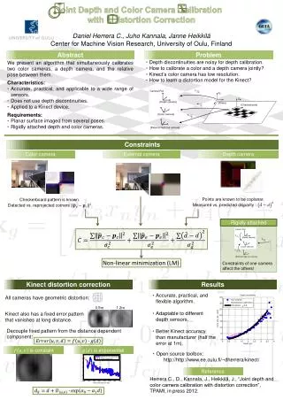
Color correction in WFS. Dichroic beamsplitter only. Dichroic beamsplitter + compensator plate. 0.6-1.0µm through-focus spots at membrane mirror Dichroic – silica, 10mm thick Compensator added to remove chromatic effects – silica, 10mm thick, @90 deg to dichroic

E N D
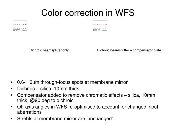
Color correction in WFS Dichroic beamsplitter only Dichroic beamsplitter + compensator plate • 0.6-1.0µm through-focus spots at membrane mirror • Dichroic – silica, 10mm thick • Compensator added to remove chromatic effects – silica, 10mm thick, @90 deg to dichroic • Off-axis angles in WFS re-optimised to account for changed input aberrations • Strehls at membrane mirror are ‘unchanged’
Changes in WFS due to added compensator plate in relay Cam2 Cam 2 • Tilt of camera mirror 2 increases from 9.5 to 14.0 degrees • Position of elements following cam 2 changes slightly • No changes in focal lengths and element sizes
Mapping deformable mirror onto lenslet array • AO modeling (Rigaut) shows that lenslet array (LA) element must be aligned within 3% of its corresponding electrode position on deformable mirror (DM) • At 51.7mm diameter DM this translates into a position tolerance of 0.16mm • Mapping determined using Zemax raytrace macro ‘raygrid.zpl’ coded by Turner (FocusSoft) and provided to us by Jim Oshman
Mapping deformable mirror onto lenslet array • Due to off-axis angles in relay and WFS there are anamorphic magnification effects in imaging DM onto LA • Raytraced magnifications of LA onto DM : x-axis = 1.72, y-axis = 1.84 • Tilting steering mirror to bring off-axis stars into center of DM results in small relative rotation of pupils. Largest rotation is for 4 corner positions (±9.32 arcsec, ±9.32 arcsec). Rotation is 0.44 degrees, equivalent to a linear translation of 0.19mm at edge of DM (compared to tolerance of 0.16mm). Acceptable • For smaller off-axis angles movements are all less than 0.16mm • Since it is easier to change electrode pattern on DM we will keep LA circular and use raytraced x and y translations to position electrodes on DM