Download
1 / 17
170 likes | 278 Views
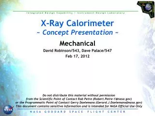
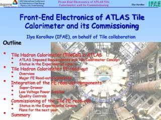
X-Ray Calorimeter ~ Concept Presentation ~. Flight Software Kequan Luu Feb 17, 2011. Agenda. Electrical Block Diagrams Flight Software Requirements Conceptual Architecture LOC Estimate for SEER Input Summary Back up charts (estimates, testing, etc.). Electrical Block Diagram.

E N D
X-Ray Calorimeter ~ Concept Presentation ~ Flight Software KequanLuu Feb 17, 2011
Agenda • Electrical Block Diagrams • Flight Software Requirements • Conceptual Architecture • LOC Estimate for SEER Input • Summary • Back up charts (estimates, testing, etc.)
Electrical Block Diagram From Electrical Presentation SpW (science Data) Calorimeter Data Processing Unit (DEEP) Calorimeter Front End Electronics (FEE) LVPS (2A) LVPS FSW Main Electronics Box ADR Control Electronics (ADRC) Power Switching & Distribution (PDU) Single Board Computer (SBC) HVPS (A/B) X-Ray Sources (2A/2B) 1pps Digital I/O FW Stepper Motor Drive (A/B) Filter wheel Stepper Motor (A/B) Low Voltage Power Supply (LVPS) S/C Power (+28V) Housekeeping (analog input) Temp, V, & I sensors Cryocooler Assembly S/C Power pulse cmd Door Actuator (A/B) status pulse cmd Vent Valve Actuator (A/B) status S/C power Survival Heaters (A/B) return Survival Temp Sensors (A/B)
Flight Software Requirements • Time Management • FSW keeps real time synch with s/c • Absolute timing requirement is 100 microseconds • Collect and CCSDS packetization of HK data including time stamping • Autonomy (e.g. operations, FDC) • Limit Checker (safemode, power & thermal monitoring, etc.) • Store Command Processor • Software Management (e.g. memory dump/load, software/table updates, etc.) • Interfaces • 1PPS and time message from Spacecraft, 100 microseconds accuracy • cPCI/SATA backplane I/O • 1553 cmd/data I/F to Spacecraft • SpaceWire science data I/F to Spacecraft and ADR • Derived • Diagnostics • VxWork/RTEMS RTOS • Bootstrap, health & Safety • Mode management • Standby, Engineering, Calibration, Observation, etc. • Instrument Support/ Science Data Processing • Command processing • Setup/Control digitizer board (i.e. detectors readout) • Signal processing - pulse characterization • Pulse template generation • Optimal filtering • Event packeting • Sun avoidance for the instrument boresight • Solar Ephemeris • Assumed s/c will provide state vector • Mechanisms Control • Multi-positions filter wheel • Thermal Support • ADR (i.e. update set-points table, recycling, FDC, etc.) • Cryocoolercmd/data handling • PID controller for the mounting plate of the ADR electronics, +/-1k stability • PID controller for the cryostat foreoptic, +/-1k stability • PID controller for FEE box, +/-1k stability • Power Switching & Distribution Services
Boot Loader Instrument Support MEB Flight SW Architecture Local Data Storage Heath & Safety File Manager Memory Limit Checker Mode Manager Checksum Manager Software HK Data Storage Scheduler Mechanism Control Solar Model Thermal Control 1553 Control Stored Commanding Commands/tables Inter-task Message Router (SW Bus) New Table EEPROM SRAM Software Bus Event Time Executive Services Services Services Services Re-engineered From LRO/GPM CFS (development completed. Deployed to GPM/MMS/LADEE for testing on target) HK telemetry Spacecraft cFE LRO Heritage
Science Data Processing Boot Loader SpaceCube Flight SW Architecture Local Data Storage Heath & Safety File Manager Memory Mode Manager Checksum Manager Software HK Data Storage Scheduler 1553 RT Commands/tables Inter-task Message Router (SW Bus) New SPW Control Table EEPROM SRAM Software Bus Event Time Executive HK telemetry Services Services Services Services Re-engineered From LRO/GPM Science Data CFS (development completed. Deployed to GPM/MMS/LADEE for testing on target) MEB Spacecraft cFE LRO Heritage
MEB Processor Utilization Estimates 72% Margin Note: The BRE440 has similar performance as the BAE750
SpaceCube 2.0Data & Processing Flow Diagram SpaceCube2.0 Science Data Processing High Data Rate Low Reliability Low Data Rate High Reliability (SIRF) Virtex 5 800x2 MIPS uB uB uB uB PPC PPC 150x4 MIPS A/D Calorimeter Front End Electronics (FEE) TMR uB 100 MIPS Virtex 5 800x2 MIPS A/D SATA PPC PPC MEB Cmd/HK 1553 I/O Memory Power Science data S/C SpW 512 MB SRAM 8 GB flash
Analysis Tools Bus Monitor FSW Development Testbeds GOLD Rule 3.06 – Dedicated ETU for flight software testing Development Workstation 1553 Ground System Front-end Sim S/C Sim MEB ETU 1PPS 1553 SpW Science Data SpaceCube ETU Cryocooler Simulator FW/Detector Simulator ADR Simulator Ethernet Cost book kept at spacecraft bus Cost captured in our Grass-root Estimate
Basis of Cost Estimate • FSW development costs estimated using SEER: System Evaluation & Estimation of Resources • Separate modules for Hardware, Software, Integrated Circuits, Manufacturability and Life Cycle • NASA-wide site license for SEER managed by Langley Research Center • The cost estimate also includes the cost of the off-the-shelf computers and tools in the FSW testbed • The IDL made in-house assumptions for FSW re-use and labor efforts; the IDL cannot confidently make assumptions about unknown vendor reuse libraries or control measures, or labor efforts or experience, so we apply GSFC reuse and labor assumptions • Grassroots test bed costs • FSW test bed simulator software development 2.0 FTEs • FSW test bed GSE $281k • $6k for 3 pieces • $15k for 1553 bus monitor • $20k for SpW bus monitor • $40k digital analyzer • $150k custom simulator hardware • $50k for software development tools and VxWorks
Summary and Recommendations • Line Of Code estimation shows 88% code reuse for MEB, 76% for SpaceCube • High heritage • No technical show-stoppers • Consider levy the 100 microseconds absolute timing requirement onto the s/c, so that the instrument does not need to include an Ultra-stable Oscillator (USO) • Perform trade to combine MEB FSW into the SpaceCube 2. If some requirements (i.e. store command, limit checker, etc.) can be moved to the s/c, perhaps the SpaceCube SIRF TMR microblaze processor can handle all mission critical requirements • Recommend acquire SpaceCube 2.0 prototype board and science data processing algorithm/software to perform benchmark to determine whether the SpaceCube is adequate for high speed science data acquisition/processing as well as mission critical command and data handling using the SIRF TMR microblaze • SpaceCube evaluation board – ML507 is ~$1500 • 0.25 FTE for code 587 to program the ML507 to X-Ray Calorimeter configuration • 0.75 FTE for code 582 (with support from the science team) to port software to ML507
Backup Slides • Development Approach • Management Approach • Verification & Validation
FSW Development Approach • Reuse LRO/GPM C&DH FSW (Med to high heritage, low risk - LRO launched 2009) • LRO FSW Features (based on 582’s Core Flight Executive) • Developed using FSW best practices consistent w/NPR 7150.2 • Onboard file systems and associated file transfer mechanisms • Onboard networks with standard interfaces • Standard application interfaces (API) for ease of development and rapid prototyping • Dynamic application loading, middleware (SB) provide dynamic cmd/tlm registration • POSIX APIs and open source Integrated Development Environment • Benefits • Will enable parallel collaborative development and system interoperability • Will automate many previously manual development activities • Will simplify technology infusion and system evolution during development and on-orbit • Will enable rapid deployment of low cost, high quality mission software • Reengineer LRO/GPM FSW for all mission specific components • Mission-specific ops concept support, thermal electronics, etc.
Management Approach • Product Development Process Will Comply with NPR 7150.2 (NASA Software Engineering Requirements and GOLD Rule) • Development • Product Development Plan per 582 branch standards, approve by Branch & Project • Detailed FSW development schedule integrated with project & subsystems schedules • Requirements management using MKStool • Monthly PSR with AETD & project; branch status reviews • Weekly system engineering meetings, FSW team meetings • FSW Design & Code reviews • Major milestones (SCR, PDR, CDR, etc) • Configuration Management • FSW CM Plan per 582 branch standards, approve by Branch & Project • Commercial CM tool (i.e., MKS) to manage source codes and document • Proposed FSW changes affecting missions requirements, cost and/or schedule will be forwarded to Project level CCB • Test Plan • FSW Test Plan per 582 branch standards, approve by Branch & Project
FSW Verification and Validation • Unit Test • Done by developers using PC tools • Follow Branch 582 Unit Level Test Standard - Tailored • Includes Path testing, Input/Output testing, Boundary testing, and Error Reporting verification • Occasionally BB H/W is required to verify H/W I/F • Build Integration Test • Done by developers to verify that the FSW performs properly on the BB H/W in the FSW testbeds using embedded system tools • First level functionality ensured for integrated software • Build Test Team to assist in GSE I/F checkout • Build Verification Test • Done by independent test team with Science Team support on the BB H/W in the FSW testbeds using embedded system tools • Test each requirement in the Flight Software Requirements documents (where possible at the build level) • Use test scenarios to test requirements in both a positive and negative fashion. • Scenarios constructed to combine requirements that are logically connected to create a test flow. • Automation to be utilized as much as possible • Requirements Traceability Matrix maintained