Download
1 / 5
50 likes | 143 Views
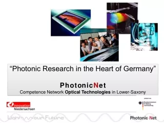
Photonic T removal techniques in the EU. G Counsell 1 , P Coad 1 , C Grisolia 2 , A. Semerok 3 , A Widdowson 1 1 EURATOM/UKAEA Fusion Association, Culham Science Centre, Abingdon, OX14 3DB, UK 2 Association EURATOM-CEA, CEA/DSM/DRFC Cadarache, 13108 St.Paul lez Durance, France

E N D
Photonic T removal techniques in the EU G Counsell1, P Coad1, C Grisolia2, A. Semerok3, A Widdowson1 1EURATOM/UKAEA Fusion Association, Culham Science Centre, Abingdon, OX14 3DB, UK 2Association EURATOM-CEA, CEA/DSM/DRFC Cadarache, 13108 St.Paul lez Durance, France 3Max-Planck-Institut für Plasmaphysik, EURATOM Association, D-85748 Garching, Germany
T-removal through ‘photonic cleaning’ • aC:H co-deposits have poor thermal conductivity compared to substrates (CFC, Be, W) • Surface heat flux leads to rapid temperature rise in co-deposit ablation or chemical ‘bond-breaking’ • Two ‘photonic cleaning’ schemes under investigation: • LASER • Flash-lamp • Requires vessel access, but can operate in high magnetic fields and in vacuuo, inert gas or atmospheric conditions • Studies on-going in both laboratory and tokamak environments and both laboratory produced and tokamak co-deposited films
Laser cleaning of TEXTOR tile • Energy density threshold for removal • Threshold factor 5 lower for co-deposit compared to graphite – selective removal • No difference between active and inert gas environment 100mm2 in 2s with 20W Ytterbium fibre laser (1060nm, 120ns, 20kHz), 2J/cm2 on f250mm spot @ 40cm 0.03 - 0.3g T/h over 150m2 • Trials conductedin JET BeHF • Co-deposit easily removed but only 10% T released micro-particulate? Galvo-scanning fibre laser developed for JET
Flash-lamp cleaning of tritiated aC:H • Photon flux from 500J, 140ms flash-lamp 3.6MW • Rep. rate 5Hz • Focused using semi-elliptical cavity – • Footprint ~30cm2 @ 30mm • 375MWm-2, 6J/cm2 • Trials now conducted using flash-lamp in JET berylium handling facility • Aim to clean thick, tritiated co-deposit from inner divertor CFC tile • Three positions treated (with varying co-deposit thickness and tritiation) • Tritium release monitored and tile sent for SIMS/IBA/SEM analysis JET 2004 trial showed engineering feasibility of flash-lamp technology
Untreated Treated 1st demonstration of T-removal • • Total T release ~9mg. • • Decreasing efficiency with number of pulses • 40% of T inventory & 70-90 mm co-deposit,removed (off gas & SEM) • 0.075g T/h over 150m2 • 7mm de-tritiation at surface of treated zone • Consistent with FE calcs of bulk heating above 700K • Build-up of Ni at surface explanation for roll-over of tritium release/pulse? (similar results for Be on other treated tiles)