Download
1 / 69
690 likes | 700 Views
Robotic Vision System. Adam Greig 2008 Systems & Control Technology Module 5 Coursework Candidate: 5039 Centre: 64859. Front Page Table of Contents Exploring Problems Initial Discussion Background Research Existing Products Questionnaire Questionnaire Results Client Comments

E N D
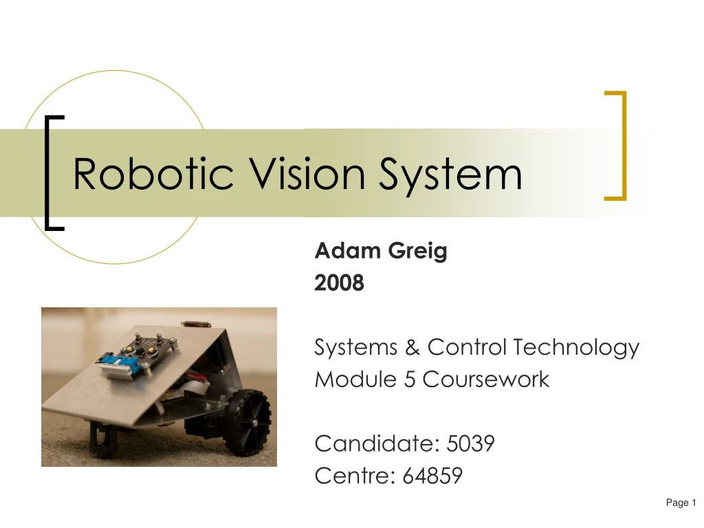
Robotic Vision System Adam Greig 2008 Systems & Control Technology Module 5 Coursework Candidate: 5039 Centre: 64859
Front Page Table of Contents Exploring Problems Initial Discussion Background Research Existing Products Questionnaire Questionnaire Results Client Comments Specifications Context, Brief and User Motor Control & Steering Servo-driven Control and Steering Development Problems Development Problems Development Problems Development Problems Development Problems Development Problems Development Problems Development Problems Development Problems Image Analysis User Interface Ergonomics Prototyping: Electronics Input/Output Table Circuit Schematic PCB Designs PCB Designs (Large View) Single Sided Design & Autorouting Alternative Circuits PCB Manufacture PCB Manufacture in Industry Reflow Soldering Testing Power Supply Servo Power Connection Programming: C Programming: C Programming: Assembler Programming: Assembler Code Motor Control Code Logic Diagram Initial Sketch Logic Diagram Possible Cases Prototyping: Casing Case Design Case 3d Views Making the Case Making the Case in Industry Final Case Final Case Final Case Final Case Case Comparison Cost Sheet Product Timeline Evaluation Improvements Appendix A: Servo Modification Appendix A Cont Attachment: Code Listing (3 pages, 8 sheets/page) Table of Contents
Exploring Problems What is the need or problem I can solve? Computer vision is a actively developing field and a simple proof of concept tracking implementation would be useful. How can I solve the problem? Using a low cost microcontroller and small digital camera to implement a colour tracking system I can develop a proof of concept. Who are the potential users? While the technology could be marketed as a toy for children, the same ideas can be used in a range of contexts, including security (as in CCTV systems that can track suspects through multiple videos) and healthcare (to monitor patients). What benefit will it bring to users? Different users will have different benefits but in general the system allows a computer to do tedious groundwork such as identifying what videos a person appears in, monitoring a patient in a hospital or at home as they move around. As a toy children would enjoy interacting with it. What might the final product be? A robot with a camera system that can track objects in its field of vision and potentially perform periphery tasks such as Does it have to conform to a standard size? It will have to be reasonably portable but size is not particularly constrained. Does it have to fit any regulations for safety of quality? As an electronics device, it would have to conform to the CE mark regulations, and as a child’s toy it should conform to the Lion Mark. Both of these specify safety and quality controls that the product must meet, as well as various ethical concerns such as advertising. To ensure safety, the device will be designed with children in mind, with no sharp edges, ideally no small parts, and a rugged construction. To ensure quality, I will be performing quality control at all points throughout the development process. What about aesthetics? It should have a fairly good looking design to encourage use, and as a child’s toy it would need to look exciting and interesting. As a pure proof of concept aesthetics would not matter. What materials and processes will I use? I will use a metal bender to bend aluminium sheet into shape, drilling holes for bolts go to though to mount components. PCBs are made industrially by photo-etching, and the components will be mounted to the board by a combination of reflow soldering and hand soldering. What is the potential price range? The robot will hopefully cost less than £100 in total. While some components are expensive, I aim to use industry standard components to reduce cost, such as small surface mount components. Is it something I can design and make? Yes. While complicated, I am capable of hand soldering the surface mounted components I will require, I am able to design the PCB on programs such as Cadsoft Eagle, and write the code for the microcontroller in a variety of editors and programming languages. The case and robot itself can be designed in CAD software such as Pro Desktop.
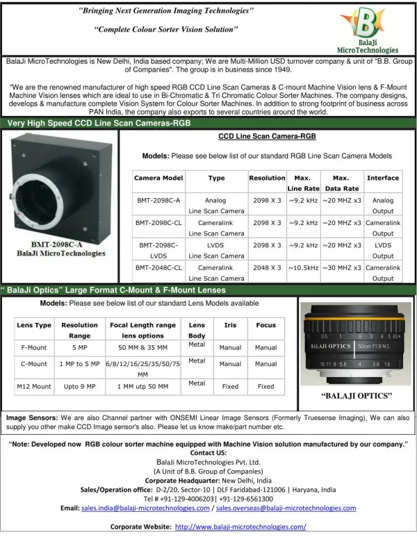
Initial Discussion Some aspects of this project are fairly advanced, and so I will address specific problems or issues related to the complexity of the project here. Surface Mounting I am using a range of components in my project, but the majority of them are surface mount. The only through-the-hole components are the connecting headers on the boards. All the resistors, capacitors, LEDs, microchips etc are surface mounted in a variety of packages.For most components I will be reflow soldering them to the PCB. This is a fairly simple process which involves putting down solder paste, placing the component and then cooking the entire PCB under a grill or similar for a few minutes. However, the power LEDs and camera unit are not suitable for reflow soldering as they contain parts that cannot withstand the heat. These components will be soldered by hand instead. ARM Microcontroller As I plan to include a form of computer vision in my project, a reasonable amount of computing power must be available to analyse the image coming from the camera. This data is streamed very fast from the camera and must be read, and also processed in real-time so the device can react quickly. The typical maximum clock speed of a PICAXE is 20MHz (with external clock source, e.g. crystal). This will give me only a few operations to deal with each byte of data sent from the camera, and no time to process it. Instead, I have selected an ARM-based microchip, in the STM32 line from ST, which has a CPU clock speed of 72MHz. This is fast enough to receive the image quickly and perform basic processing on it, as well as handle periphery tasks such as motor control, accessing a memory card, GPS subsystem, etc. SD Card I plan to include an SD memory card in my project. This is a format for memory cards capable of storing up to 8GB of data. They can be written to using a standard protocol for microcontrollers, namely SPI. I do not believe writing to the SD card will present an insurmountable challenge. If it is more complicated than I have time to implement, there are also available microchips which will write to an SD card and receive data and commands over a serial connection, which would simplify my programming. OLED Screen I also plan on using an OLED (Organic Light Emitting Diode) screen, instead of a standard LCD. It has extremely low current consumption compared to an LCD, and yet is very bright and can be read in all lighting conditions. The screen I have available is small but very easy to control, as commands are simply written over the serial port to a display driver integrated with the screen, allowing simple shapes, texts and graphics to be displayed. Camera In order to identify the user, I will have to use a camera system. The most readily available one is a small surface mounted component which has an I2C interface for control and sends out data over an 8-bit parallel interface. The microcontroller I am planning to use can use I2C as well as read in the data over the parallel interface, so should be able to receive camera data. Processing the imagery is another problem. I plan to look for the centre of mass of a specific colour. The camera data gives me the red, green and blue values for each pixel and I can compare these against a reference value that represents the colour I’m looking to find. If the colour is close to my reference colour, I can store its pixel address. Once the entire image has been processed and all matching pixels found, I can determine the centre of the mass for the matching pixels by summing all the x positions and dividing by the number of pixels, then summing all the y positions and dividing by the number of pixels again. This gives me an x, y coordinate for the centre of the colour zone. By comparing this against the centre of the image, I can determine whether the coloured zone is to the left or right of the robot and how far away. This enables me to steer to face the coloured zone. By comparing the number of pixels detected to an internal reference value I can also estimate how far away the coloured zone is – for instance, if I know that with 300 pixels visible the object is 1 metre away, I can determine approximate distance for any other pixel value. This allows me to drive towards the coloured zone.
Background Research Fiducial Marks Market The children’s toy market is massive, worth £2.1b in the UK alone, and grows steadily with the constant introduction of new customers. However, recently growth has declined as children are “getting older younger” – they lose their interest in toys and start to want DVDs, games, music and makeup more than the latest toy. Toy manufacturers are increasing their use of technology to keep the toys attractive to children, as well as reducing the development time of the toys, allowing them to get more on the market quicker. The extra technology also allows them to charge more for the toys, increasing revenue. Mattel’s Barbie brand was declining rapidly in 2005, to the point where it was no longer on the Toy Retailers Association’s “DreamToys” list, a list of toys they believe will be very popular at Christmas. Mattel renewed the brand by adding technology to the otherwise plain Barbie dolls, such as DVDs as interactive accessories. These successfully brought Barbie back to the DreamToys list. That list is now full of high tech toys, from a voice changing helmet to battery operated Tiggers that dance along to music. Technology is evidently becoming a more important factor in children’s toys, and there is clearly a large market for it. My product features fairly advanced technology compared to most toys, and as a result would be a high-end toy that could probably sell well and at a high price point. Advertising is important for children’s toys and a good advertising program could generate demand for the toy. Use The toy must be simple to use as it is for use by children, and as such the basic operation consists just of switching it on and wearing the brightly coloured jacket. The robot then tracks you. To perform more advanced features such as changing the colour to be tracked and saving photographs the menu interface is used, which has a bright colour screen and simple button interface. Other Research Computer vision is a large field in signal processing and what I aim to accomplish – simple tracking of a colour area – is relatively simple compared to what might be accomplished. The microprocessor I am using has enough power to potentially perform more complicated operations, such as feature tracking, optical flow calculations, face and pattern recognition. These processes are all considerably more complicated than the simple colour tracking, but would provide additional functionality, especially as a user may not always be wearing a simple block of colour for colour tracking. Stereo video systems are also often used as they allow the robot to determine depth to objects, making tracking more accurate. For my project, this was not required and would have involved considerable additional cost and complexity. Computer vision itself is widely used throughout industry and is being constantly developed. One example is pick and place robots that are equipped with cameras so they can identify the component they are picking up and where to place it. Typically there will be a camera above the PCB to be assembled, and often one below it as well. Alignment marks on the PCB, known as fiducial marks, are precisely positioned and the pick and place robot’s camera will detect these and therefore be able to position the components very accurately relative to these markers. This technology has increased the speed and accuracy of pick and place robots, reducing the total time and cost of assembling a PCB board. Another use for computer vision technology is in new digital cameras which can detect where a face occurs in the image and optimise the camera’s settings to get the best exposure on the face, which is usually the most important part of the image. This improves the quality of many photos taken with a digital camera without needing to increase the technical capabilities, instead the existing settings are fine tuned to the detected face. An example of a fiducial mark. A second mark is visible at the top of the photo. The camera will align to these to know where it is relative to the PCB. Fiducials can be placed in many positions on the panel. Panel fiducials do not show up in the final PCB and can be used for rough alignment. The global fiducials align components all over the PCB, while local fiducials provide high levels of accuracy for fine pitch components. Some example fiducial shapes. The circle on the left is the most common.
Existing Products Conclusion: From my product research I can see that many current robots designed to be toys have a wide range of sensors and are typically designed to emulate real life animals, making them more like pets. They are also typically very expensive, probably as a result of the range of sensors inside. They also have very sophisticated mechanisms inside to move the legs and head in a lifelike fashion, but I will not have the time to do this. My robot will not be emulating an animal as it simply follows the user.
Questionnaire As my project is more a concept demonstration than an actual product my questionnaire contains mostly technical questions regarding the systems in the project than questions about end user requirements. 1. What types of sensors do you think are appropriate for a tracking robot? a) Camera b) GPS c) Ultrasound d) IR Rangefinder 2. What power supply would you want on an autonomous robot? a) NiMh b) NiCad c) Li-Ion d) Li-poly 3. How fast should the robot move? a) 1m/s b) 3m/s c) 5m/s d) 10m/s 4. What user interface would you think is appropriate? a) Buttons and LCD with text b) Buttons and LCD with text and graphics c) PC link for control only d) PC link for control and image 5. What recording capabilities would be appropriate? a) SD card b) SDHC Card c) Wireless uplink d) CD/DVD 6. What illumination should the robot use? a) Standard LEDs b) Power LEDs c) Filiment bulbs d) Xenon bulbs 7. What material should the casing be made of? a) ABS b) Polystyrene c) Aluminium d) Steel 8. What should the robot track on? a) Colour b) Pattern c) Movement d) A combination thereof 9. Do you think it would be useful to have add-on capability e.g. for GPS a) Yes b) No 10. What price boundary would be appropriate for a working prototype a) <£100 b) <£500 c) <£1000 d) <£5000
Questionnaire Results As my project is more a concept demonstration than an actual product my questionnaire contains mostly technical questions regarding the systems in the project than questions about end user requirements. Results All questions generally had a consensus agreement which for the most part is what I will be doing. The camera was decided as the most appropriate sensor which is what I will be implementing. An SD card will be used to record as it provides reasonable storage space in a small and common format. I am making the case out of aluminium which is strong, light and easy to work with and will hopefully be within the suggested price boundary. I am using Li-Poly batteries as they provide a useful voltage and have a high energy density, allowing the robot to run for longer. Power LEDs provide cheap and bright illumination which are also easy to control. Tracking is more of a contention as while a pattern or combination scheme would be more powerful, it is much more difficult to implement in real time so I will be tracking by colour. For the user interface an LCD was the most popular as it provides onboard feedback without requiring an external computer, and having graphics on the LCD provides more feedback and lets the user see exactly what the camera sees, so is what I will be doing. 5 m/s was the most popular movement speed but as I will be using modified servos I have less control on speed, instead they are easy to interface with and mount without requiring additional circuitry. While generally addons were a popular idea it is unlikely I will be able to implement it on my time and cost budget.
Client Comments “It should be able to run for at least half an hour without recharging” Advanced lithium-polymer batteries provide a long runtime on the order of an hour or so. “It should be able to work in the dark” LED headlights provide illumination in low light levels which the camera can detect “I want to be able to store what it sees for later” An onboard SD card stores images to be viewed on the computer later “The batteries should be rechargeable” Lithium polymer batteries are very, very quick to recharge and can be recharged many times over “It must be able to recognise a new thing to track without being reprogrammed” The menu on the screen on the back of the robot will allow the user to select a new colour to track.
Specifications Maintenance No parts should require maintenance however due to its prototype nature I will allowed for easy access to circuitry and internal wiring for debugging etc. The structure would be left open on the sides so that I can easily reach in to connect probes or change switches etc. Safety My robot uses low voltage and current so even if the user shorts a circuit they will not receive a dangerous shock. Plastic connecters will be used for wires so there are no exposed contacts for the user to touch, and the metal casing uses bent edges so is not sharp. The robot will not be able to move fast enough to cause any serious damage. The main safety issue will be the power source, as I will probably use lithium polymer batteries which provide a high energy density however can explode violently if short circuited. The batteries I would use have a small circuit built into them which prevents short circuiting, so the batteries can not explode. Cost As this is a proof of concept which will use advanced components and industrially made PCBs I expect it to cost quite a lot. As my time and labour is not charged I expect the cost will be very low compared tomost commercial prototypes but nevertheless it willbe expensive for a school project! Performance Must be able to track the user and follow them Must be able to light up the area if it is dark Must have a user interface so the user can select a mode of operation Must be able to store photos or videos taken with the camera Must be sturdy and reliable Must be able to keep up with the user at a walking pace Must be simple to use Ergonomics As the robot is not designed to be handled, my aim is to make the robot as small and compact as possible. Aesthetics The robot should look reasonably modern and high-tech however as it is a proof of concept the actual look does not matter. Manufacture Techniques will be used which are readily accessible to me such as metal bending, vacuum forming and reflow soldering. The college mainly uses through the hole technology however I will be using surface mounting with reflow soldering as I feel this is within my abilities to achieve, is a more realistic industrial process and allows me to use components not available in through the hole packages e.g. ARM microchips which allow me access to increased processing power, which I suspect I will need. This laptop has suffered damage from exploding lithium polymer batteries.
Context, Brief and User Context and User Currently computer vision is used in a wide range of fields where automated detection and recognition is required. Examples include pick and place robots used to assemble components on PCBs, which can automatically detect the component required with cameras and then place it very precisely on the PCB by aligning itself with fiducial marks (see background research page). Other uses include security systems that can automatically identify someone by their face, or follow one person through many video feeds by looking for their face. Civilian uses include digital cameras that can automatically detect faces in the image and adjust the focus and exposure to get the best quality faces, and modern cameras can even detect if someone blinked at the moment you took the photo and take another automatically. At the moment computer vision systems are mainly used to identify controlled patterns, for instance fiducial marks or some 2d barcodes, or things that are relatively the same and just need to be searched for e.g. faces. However more advanced systems will probably be able to perform more complicated tasks and determine more about their environment in less controlled conditions. An example of an advanced system would be a car that could detect where it was (possibly using GPS) and then use camera systems to identify the road, look for any road hazards such as other cars or pedestrians, and then safely drive the car within the speed limit and react quicker to events than a human would be able to. Vision systems are likely to become a widely used source of information for systems in the future as they are capable of providing a vast amount of information which can be analysed to determine a lot of information, and as it is very similar to a person’s primary sensory input it is intuitive for people to understand, unlike for instance ultrasonic distance sensors. The current problems mainly involve the sheer amount of data and the difficulty in analysing it. Current systems are designed on linear imperative programming where one command is executed at a time and mass parallisation is not available. This means that images take a long time to process and require fast processors. However, increasing processor speeds and increasing number of ‘cores’ will enable faster and more parallel processing of images. Other systems such as neural networks can process images in parallel even faster, and as these become widespread it is likely that vision systems will be used more and more. Computer vision follows a general trend today towards more intuitive interfaces to computer systems, including developments such as advanced, accurate touch screens that can register multiple touches at once, and display developments such as 3D screens. Brief I will be building a system that uses a vision system to identify specific items in its field of vision and then drives towards them. If this basic idea can be shown to work then the same concept could be easily expanded to many other fields, such as a stationary camera that can track users moving past it. Due to the simplicity of obtaining the central point of a continuous coloured region I will be having the system identify this region and calculate its central point, giving it a position to move towards. If the user wears clothing with a continuous block of colour, such as a bright red t-shirt, then the system would be able to identify them and determine their position relative to itself. This information could be used to move towards the user and therefore follow them, or used to activate some other function such as storing a photograph. To implement this I will be using a small camera, a powerful microchip to process the data, some kind of storage mechanism to store images if required, a screen and switches for a user interface and a method of movement in order to follow the user.
Motor Control & Steering Motor Control I could use DC motors to drive my robot. They would be connected to a compound gearbox to increase the torque, as ungeared they have a high rotational speed and low torque. To control speed and direction, I would connect the motors to an H-Bridge, allowing for completely automated microprocessor control of the motors. The four FETs used in the H-Bridge can be switched on and off to set the direction, and pulse width modulation can be used to alter the duty cycle, which controls speed without significantly reducing torque. The four FETs are also available as a single microchip which connects to the motors and to the microchip. This makes design easier and circuits can be smaller. The microchips also contain short circuit protection which makes it impossible to accidentally short circuit the power supply by turning on two connected FETs together. This could happen on an H-Bridge made out of discrete transistors and could potentially damage the transistors and waste battery power. The H-Bridge microchips also allow the direction to be controlled using just two outputs from the microprocessor, reducing programming complexity. Motor Mounting There are a variety of ways I could mount motors on my robot. I could mount four motors and use a servo to control the steering of all four independently, giving me four wheel drive as well as letting the robot drive sideways. However, this is more complicated to control and costs more. Another option is to mount four wheels with the motors on each side in parallel, giving four driven wheels but using differential drive for steering, in other words sending one side in reverse and one side forward to turn. A modification on this design is to just use two motors at the back and a runner or wheel on a caster at the front, allowing the robot to steer in the same way and the front just runs along the ground. The robot then turns around the centre of the two wheels, instead of its own centre. Four wheels with differential drive Two wheels with differential drive Four individually steered motors Runner Centre of rotation Four wheels Four wheels This circuit design shows how an H-bridge is wired. The four FETs control current flowing through the motor. By turning on alternate pairs, you can reverse the direction of the motor. This is represented by the two buttons which each turn on two FETs. Centre of rotation Centre of rotation Two wheels Servos steer each wheel Four motors Two motors Four motors Advantages:Can drive sidewaysTurns about the centreMore complicated steering is possibleCan move forwards while turning, like a car Disadvantages:Costs more in componentsMore complicated to control Advantages:Turns about the centreSimple to controlFour wheels gives lots of torqueMid-range price Disadvantages:Can only steer by turning about its centre while stopped Advantages:CheapestEasiest circuit design because only two motor drives and two motors Disadvantages:Turns at the backMust stop and turn, can’t drive while turningTwo wheels do not give as much torque
Servo-driven Control and Steering Servos Normally, servos are designed to rotate to a fixed position depending on the length of an input pulse from a microcontroller. This makes them easy to use with microchips as all required circuitry is in the servo case, along with the motor and required gearings. Internally, a potentiometer is used to measure the position of the output shaft, and the circuitry inside then moves the motor until the correct output position is obtained. However, with a simple modification the servo can rotate continuously, and the length of the input pulse from the microchip determines movement direction and speed. I will be using two modified servos to drive my robot, as they are reasonably powerful, small, easy to control and require no external circuitry. The only interface needed to my main processor is one PWM line per servo. Compared to motors, servos are easier to control, are often physically smaller, and they do not require external gearboxes or H-bridge circuits.They are also cheaper and use much less PCB space for additional control components. Modifying the Servos The modification involves two main steps. First, the servo is opened up and the gears removed so the control potentiometer is accessible. The servo is then connected to a microcontroller which sends it a middle-position pulse. The potentiometer is then adjusted by hand until the motor stops, i.e. the servo now believes the output is in the middle. The control potentiometer is then cut off so it does not interface with the output shaft, and then it is superglued in place so it cannot move. The second part removes the mechanical stop on the output gear that would normally prevent the gear from rotating in a full circle. This stop is a small plastic tab that will normally not be able to move past the gear behind, preventing the servo from rotating beyond its normal movement range. By snipping this tab off and filing it down, it is possible to allow the output gear to freely rotate over a full 360 degrees. With both modifications performed the servo Is put back together and now sending a pulse that would send the output to the middle (180 degrees) will stop the servo, sending one that would send the output to 90 degrees will drive the servo in full reverse and sending one for 270 degrees will drive the servo in full forward. Sending a pulse between the extremes drives the servo at a slower speed. See Appendix A for full details of the modification. Differential Drive As discussed on the previous page, I will use differential drive to control the robot. Two servos are mounted at the back with a runner in the front, and then the robot is driven forwards or backwards when both servos move forward and backward, and steers left and right when one servo is going forward and the other backwards. Left to right: The original servo, Manually setting the control potentiometer to the middle position, Snipping off the mechanical stop
Development Problems Programming the ARM chip There were several problems that had to be overcome in order to program the ARM chips. This was compounded by the lack of documentation, as most of the information I could find was targeted at commercial users who use professional Integrated Development Environments (IDEs), which cost a fair amount of money and do most of the hard work for you. As I will not be using an IDE, this documentation was not particularly useful for me. I was eventually able to find an example program that I would be able to use to test programming. The first stage of programming the ARM is writing compatible C code. I solved this problem once the rest of the programming was successful, as only then was I able to test my own code. I use a library provided by ST, the manufacturer of the microchip, which provides easier access to the chip’s onboard peripherals such as the timers, ADC, SPI port etc. The library itself is fairly well documented so I was able to quickly get the hang of how to use it. However, each program also needs to set up the microchip to its own specification, for example setting the clock multiplier to determine the chip’s clock speed, initialising peripherals, etc. This was difficult to determine without sample code, and there are many different but equally valid ways of doing it. I eventually made a successful piece of code to initialise the clock and set up the required peripherals. The second stage is compiling the C code into a binary file that can be sent to the ARM. To do this, a compiler is required to make object files from the C code, and then a linker is required to produce the output binary. These programs are typically available together as a toolchain. The free and open source toolchain GNU toolchain offers some support for ARMs, but a modified version produced by CodeSourcery (and also free and open source) supports a wider range of microchips, including the one I will be using. Obtaining the toolchain was not a problem, but successfully compiling and installing it took several hours until I was able to compile a sample C program into a binary file. The third and final stage is uploading the binary file to the microchip. This uses another program, OpenOCD. OpenOCD had to be compiled and installed, which was not a problem, but also requires a configuration file. There was little documentation on what this file requires, and all the examples I was able to find were for an older version of OpenOCD, which uses a different set of commands for the configuration file. I was eventually able to create a suitable file that could program my microcontroller by comparing the incompatible examples with the new set of commands. Once this was made, I was able to upload a sample program to the microchip successfully, and obtained a blinking LED – the “hello world” of embedded microchips!
Development Problems Hardware Modifications There were a few features on the circuit boards which needed modification. As the circuit boards take time and money to manufacture, I decided to perform the modifications on the circuit board rather than by altering the design. On the main controller board, the ARM’s analogue positive power supply (AVDD) was connected to ground instead of +3.3V, and similarly the analogue negative power supply (AVSS) was connected to +3.3V instead of ground. This resulted in a short-circuit inside the ARM when the circuit was powered up. Luckily, next to both analogue power supply pins were the analogue reference pins, which were connected to the correct level. To fix the problem, the microchip’s pins for analogue positive and negative were cut so they did not make contract with the PCB, and then they were soldered to the pins next to them. This successfully solved the problem. On the camera PCB, pull-up resistors had not been added to the I2C bus lines, and as this is an open drain bus they are required. Small 10k resistors were added on the underside of the board, connected to vias (plated through holes connecting copper on the two layers of the board) on the SDA and SCL lines and also to 2.8V. This means they are small and difficult to see from the front of the robot, and as they simply soldered into existing vias there was no need to actually modify the PCB. Similarly there was no pull up resistor on the reset line, and while this shouldn’t have been an issue one was added in case. The MOSFET originally planned for use on the camera PCB had a reverse Schmitt diode in parallel with the FET internally, and this had a large voltage drop which meant the power LEDs lit up very dimly, so would not be useful as headlights. The MOSFET was cut out and replaced with a power transistor with a 10k resistor in series with the base to limit current. This allowed the LEDs to light up much brighter. Note: The pitch on these pins is 0.4mm!
Development Problems Interfacing with the Camera – I2C The camera unit I will be using is designed for embedded systems such as mobile phones, and as such has not been designed to be easy to interface with. The camera is controlled over an I2C connection, a two-wire communication bus that allows for up to 127 devices per bus and is fairly easy to implement. The two wires are named SCL (clock) and SDA (data), and the data line is bidirectional. The entire bus is open-drain, which means a device pulls the line low to signal a 0 and does nothing to signal a 1, so pull-up resistors are used to pull the bus lines to the correct voltage. In I2C terminology, the “master” is the device that initiates the communications, in this case my ARM, and the “slave” is the device that responds to requests from the master. Data can be transferred from master to slave or slave to master. The ARM I am using has two built-in I2C interfaces which are controlled by hardware. This allows me to use the I2C bus by simply issuing commands such as “I2CGenerateSTART” to start a communication, and send data by writing a byte to the relevant register. The camera datasheet gives a very brief overview of the standard I2C protocol. First, a START condition is generated, which consists of the data line being pulled low and then the clock line shortly afterwards. The address of the slave is sent by pulling the data line low or leaving it high and then pulsing the clock line. Data is valid when the clock line is high. The slave address is 7 bits, and for the camera is 0111100. The eighth bit of the first byte sent is a direction bit, 0 for write and 1 for read. This indicates whether the master will be reading or writing to or from the device. Once the slave address is sent, the slave should acknowledge it by pulling the data line low on the 9th clock pulse. If the slave does not acknowledge its address, it leaves the clock line high and the ARM does not continue communications. The ARM library I use asks for a 7 bit address to send and I initially supplied 00111100, and then told the library I wanted to write to the device (0). This should have generated the byte 0111100 0, and the camera should have acknowledged it. However no acknowledgment was received. I2C happens far too fast to debug using a visual indicator and I did not want to spend a long time editing the code bit by bit to try and solve the problem with guesswork, so instead I built an improvised logic analyser, a device which reads the state of several lines at once and shows a trace of their state over time on the screen. As commercial logic analysers are expensive I simply connected wires to my parallel port and connected these to the I2C lines on my robot, and using open source software which reads the parallel port and plots it on the screen I was able to obtain a trace of what was happening, shown below. The white text was added by me to help show what was going on. The top line is the clock and each of the 9 pulses generated are clearly visible and numbered. The bottom line shows the data being transferred and its state is read when the clock line is high. Each vertical grey line represents one sample of the parallel port. The start signal occurred before this trace started which is why both lines start low. The clock line then goes high nine times and it is easy to see that the ARM is in fact sending 00111100, and the camera is then not acknowledging its address. I quickly saw that the address was effectively shifted one bit to the right, so updated the address the software was sending to be 01111000 and tried again.
Development Problems Interfacing with the Camera – I2C Continued Once the correct address was being sent to the camera the rest of the I2C communications went without a problem. The trace below shows the set-up procedure and a test read of the data to confirm correct operations. The camera’s data sheet gives a list of all its registers and their default values, so I had my ARM read a sample register to see what the camera returned. The trace below shows the clock trace at the top which is pulsing for each bit of data. The data line at the bottom shows what my ARM is sending and receiving. Green lines indicate each byte (nine clock pulses as each byte is followed by an acknowledge) and red lines indicate a start/stop condition (start is when the data line is brought low and then the clock line follows while end is when the clock line goes high and the data line follows). In the first byte the camera’s address is sent and the camera acknowledges its address. The register to be written to, 0x03 or 00000011 is sent and the camera again acknowledges. The new data to be written, 0x22 or 00010001, which turns the camera on and selects RGB mode, is sent and the camera acknowledges. That is the end of the first communication and a STOP condition is generated. To read the test register, a START condition is first generated, then the camera’s address is sent again and it acknowledges, then the register to be read is selected (0x22, or 00010001) and a second START condition is generated. The camera’s address is sent again, but this time the 8th bit is set to 1 to indicate that the master will read from the slave. The camera then starts sending the register data, 01011000 and does not receive an acknowledgement from my ARM, so sends no more data. The ARM continues generating a clock pulse for one more byte then acknowledges the final byte (which it read as 0xFF or 11111111) and generates a STOP condition, ending the communication. At this stage I know the camera’s circuitry is operating correctly, that it is receiving power and its internal state is what I expect from the datasheet. It is also now sending data to my ARM over the actual data transfer lines.
Development Problems Interfacing with the Camera – Image Data The camera module I am using, once configured over I2C, simply streams image data along with a data clock signal and two synchronisation pulses (a vertical sync for each new frame and a horizontal sync for each new line, VD and HD respectively). The image data is not buffered or clocked out by my microchip so the microchip must synchronise to the image data to successfully receive all the image. This is made more difficult because each pixel of image data is made up of two bytes of colour data (to give 16bit colour). This means that to successfully read in any given pixel, two successive bytes must be read in and they must be in the right order. As a result, reading in random bytes – for instance every third – results in noise. The camera’s datasheet did list some signal timings but without enough detail to reveal what the camera was actually sending, and additionally I did not know what image the camera was supposed to be sending. I configured the camera to send a test image made of colour bars, which would make knowing I had the correct image easier. However I did not know what the test screen was supposed to look like and it was not specified in the datasheet. To make solving these problems easier I used a small logic analyser. It samples at 24MHz, which is fast enough for all the signals involved in this project, and has eight input lines which is enough to monitor all the data lines together if nothing else is being read. I went through several methods to attempt to read in the camera data perfectly, with varying success. Typically the complexity of the method was correlated to the levels of success! Since my microchip has limited RAM I initially only attempted to read in the first 32 pixels of the first 24 lines, giving a small image of the top left corner of the full sized image. The first method I tried had two nested for loops, the outer one iterating over each line and the inner one iterating over each pixel. In the inner loop the microchip polled the data clock line to wait for it to rise, then checked if current pixel and line count were within the 24,32 limit. If so, the input data register for the port the camera is connected to was ANDed with 0xFF to select the lower eight bits, and this was shifted right by 8 to store the first byte in the upper eight bits of a 16 bit variable. The microchip then waited for the data clock (DCLK) to rise again before reading in the second byte, this time ORing it with the existing 16 bit variable to store the second byte in the lower 8 bits. The data was then read out to the OLED screen, which takes 16bit RGB data. The data from the camera is in BGR, in other words BBBBBGGGGGGRRRRR while the screen requires the data in the other order so I converted each byte to RGB before sending to the screen. This method produced some colour on the screen but it was certainly not a test pattern and mostly looked like random noise. The code for each pixel took far too much time and was not accurately synchronised to the signals provided by the camera. The first improvement I made was to only loop through the first 24 lines and only 32 pixels in each line, and went to sending the data after this. This method removed the check at each pixel which helped but the screen still did not display a consistent pattern. The next improvement I made was to wait a certain amount of time instead of waiting for the clock signal as it appeared it might have been too slow in reacting to the clock signal. This did not make much of a difference. After that I unrolled the loop, in other words instead of a for loop running 32 times I had the same piece of code 32 times to read in the data, with a fixed wait between each byte. This method worked a lot better and I was able to get two bars on the screen, however they were not a solid block of colour and it appeared as though the camera was not synchronising to the data clock successful, running into the problem I mentioned earlier that each pixel required two successive bytes be read successfully. With this method I disabled the test pattern and could just about make out simple shapes in the camera output. This photograph shows the screen with the camera not in test mode, using the final method described above. A CD is being held in front of the robot, and the screen is showing the top left corner of it. Next to the photograph is a rough sketch of what is being shown without the diagonal noise. The larger cyan area is the white part of the CD while the brown inner part is the inner ring and finally there is a hole in the centre. The shape seems to be correct but the colours are clearly wrong.
Development Problems At first I connected the logic analyser to the I2C lines to check the camera was being initialised correctly at high speed, where the previous logic analyser using the parallel port was not capable of reading the signals fast enough. The initialisation was being performed without any issues. Next I connected up the data clock, horizontal sync, vertical sync and three data lines. This let me see when images started after the initialisation, what speed the clock pulses were coming in at, and when the data changed relative to the data clock. Interfacing with the Camera – Image Data I adjusted the delay timings for a while without much success getting the image to be better synchronised. As it stood, each new frame was different even when the camera was generating a static test pattern. This indicated that the microchip was not synchronised to the camera properly. However, I still was not sure what the camera was supposed to be sending. At this point I got the logic analyser and connected it up to see what the camera was sending. The logic analyser has small probes which I connect up to the pins on the 20 pin header on the camera PCB, as they exposed and easy to connect to without damaging the circuit, As the logic analyser only has eight inputs I connected it to the I2C lines, the sync lines, some data lines and some clock lines depending on what I wanted to see. At first I wanted to see how the data signals related to the sync signals so I connected it to DCLK, HD and VD as well as five data bits. Once I know what pattern the data went in and how it related to the sync signals I connected the logic analyser to all eight data bits to read off what the actual data the microchip should be receiving was. This screenshot of the logic analyser program shows the start of one image frame. The VD line is the vertical sync. It drops low just before a new frame starts, and then the frame starts when it rises again. VD, the vertical sync, is high while each line of data is sent out. It rises the first time to indicate the first line of data, which is clocked out using the data clock. Looking at this data trace I can see that there is a lot of space between each line being sent out, so I could potentially analyse that line in this space between lines. Additionally there is a further space between each group of four lines which could be used to catch up with any buffered data. The bottom three lines show data being sent out and they correspond to the lines, as this is where data is being sent.
Development Problems Interfacing with the Camera – Image Data This screenshot is zoomed in a bit. The vertical sync line rises, indicating a new frame, and shortly afterwards the HD line pulses indicating one line of data. While the HD line is high transitions are observed on the data lines. As the camera is currently configured to show a test image, made up of eight vertical coloured bars, we can see from just these first three bits of data that there are eight different colours being sent. Further zoomed in, the image data can be seen clearly and the eight different coloured bars can be seen. Zoomed in further still the data clock is now distinguishable. Measuring the time between pulses shows the frequency of the data clock to be 2MHz. The data clearly changes as the data clock falls, is valid when the data clock rises, and then changes again when the data clock next falls. Using this data has allowed me to decide how my program will read the data from the camera, at what speed and when in the clock cycle. I can see that I will need to wait for the VD line to rise, and then get ready for the HD line to rises. Once HD rises, I can see that the data clock will be low, so I then wait for the data clock to rise and read the data at that moment, then wait for the data clock to fall and rise again before reading it again. Once each line is read in I know I have a reasonable amount of time before the next line will arrive, which should be enough to process that line of data allowing real time analysis.
Development Problems Interfacing with the Camera – Image Data One problem I faced, now that I could see some amount of actual image data, was that all the colours were incorrect. This is a significant problem if I plan to track based on coloured objects. After a while looking at what data was being sent when I held plainly coloured objects in front of the camera I realised that the pattern the datasheet specified for the data was incorrect. The datasheet supplied with the camera state d that the data was sent in the form BBBBBGGGGGGRRRRR , while in reality the camera is sending RRRRRGGGGGGBBBBB. This simplified my post-processing on the image data as this is the same format as the OLED screen, so I can just send the data directly. However there was still colour noise to either side of the small part of the image I was looking at, corresponding to the slight shifts in the data clock as my microchip goes out of phase with the data clock. To fix this, I reprogrammed the interrupt handler for the horizontal clock signal in assembler. When programming in assembler each instruction executes in one clock cycle (for most instructions), and as the microchip runs at 72MHz this gives a lot more performance than the C code that compiled to several assembler instructions per line. I was able to write a handler in assembler that took 7 commands to read in the data and a few more to synchronise to the data clock. By having the handler synchronise to the actual data clock the problem with colour noise was resolved and the data coming in was exactly what the camera sent. At this point the image on the screen matched reality fairly well – pointing it at a coloured targets shows the correct colours on the screen, faces are clearly recognisable etc. The main problem at this point was that the microchip could only hold a very small section of the image in its RAM – 24 by 32 pixels, approximately. The screen is sent data over serial and cannot be sent data in real time, so the image data has to be buffered inside the microchip before being sent out. To improve the displayed image I obtained a small LCD designed to be embedded in mobile phones, with a resolution of 128x96, the same as the small-sized image sent by the camera. This screen is updated over SPI, which can be written at speeds up to around 10MHz, fast enough to send the data from the camera in the time between new lines. The screen can connect to the same header that normally connects to the SD card, so no circuit modifications were needed. I made a small PCB with a 2.8V voltage regulator, two LEDs and the screen along with a backlight unit for the screen. The microchip has dedicated DMA circuitry that can access all the main peripherals. This means I can configure a DMA circuit before starting to read in image data, telling it where in memory to start reading data and how many bytes to read. Then, after the assembler code has finished reading in each line’s data, the DMA circuit can be triggered, which will automatically start sending data from the memory to the screen over SPI. At the same time, other code can be running, which means I would be able to analyse the image at the same time as it is displayed on the screen. With this knowledge I continued trying to get my program to read in the image data. The next iteration of the code replaced the loop in the main code with an interrupt driven design. The HD and VD lines were connected to the interrupt generator so that an interrupt would be called when the lines rose. The main code then enabled the vertical sync interrupt and idled waiting for data to be fully collected. The vertical sync interrupt code simply enabled the horizontal sync interrupt code. Initially I had the horizontal sync interrupt activate an interrupt on the data clock, which then stored the incoming data in the memory array. This method was far too slow and as a result the image data was completely inaccurate. The next attempt removed the interrupt on the data clock and instead tried to read the data clock in the horizontal interrupt code. This method was also too slow. Next I went back to a timed delay between reading in each pixel. This method worked fairly well but had random colour noise at various parts of the image where my code went slightly out of phase with the data. This did produce a fairly good image on the screen but only for a small section of the image. In the photograph below the colour noise can be seen at either side while the image is readable in the middle. The photograph is of the OLED screen on the back of the robot. Two images showing “HELLO WORLD” and “A” respectively. The piece of paper being held in front of the camera
Development Problems Interfacing with the Camera – Image Data With the small LCD connected I modified the code to first send a sequence of initialisation commands over SPI, and then set up a DMA channel that was configured to send 256 bytes of data, starting from a specific memory address that is the start of the image data, to a specific peripheral memory address (the SPI port), auto-incrementing the memory pointer and stopping when the data is all sent. The SPI port was configured at 18MHz, several times faster than the data is coming in from the camera. The code to store the image data was modified so that each line is stored and then next line the previous data is written over – only one line is stored at a time. Originally I used C commands to trigger the DMA channel after each line but this was far too slow to be useful. I rewrote that part of the code in assembler as well and as a result the entire thing ran fast enough to send each line of data to the screen in plenty of time before the next line. This means the screen shows exactly what the camera sees, in real time. The resulting image updates at approximately 5fps so displays fairly smooth video with accurate, albeit 16-bit, colour. A logic trace of the horizontal sync from the camera and the SPI outputs. It is clear that the data is sent over SPI in plenty of time for the next line of data from the camera – 0.12ms for the data from the camera compared to 0.11ms for sending the data over serial. There is ample time to analyse the data between lines. Each pulse on the HD line represents one line of data being sent from the camera, while each solid block on the SPI lines show the data being sent out over them in serial. Two images from the camera displaying on the screen. The large metal plate behind the camera is the backlight unit, which can also have a larger LCD mounted on the back. The image data is now captured successfully. The next problem is processing it to determine what direction to move the robot.
Image Analysis To determine if any particular pixel is the correct colour, I break it down into three components (red, green and blue) and then look at each one to decide if their values are within a threshold. Experimental testing showed that red values above 22 and green and blue below 13 were suitable for a small piece of red plastic I was using as a test subject. Since the code must also perform as efficiently as possible I break down the analysis code. The data for each pixel starts as a two-byte combination of all three colour components. First I extract the red value by ANDing the two data bytes with a bitmask that selects the 5 most significant bits. In the same operation the red values are shifted down by 11 places by the hardware barrel shifter. This leaves me with a number between 0 and 31 representing the red value. I then compare this value to my constant and jump to further analysis code only if the red value is greater than my constant. I then separate the blue and green values in the same way and compare them, each time jumping to the next piece of code if they match. If the pixel matches entirely, I add its x value (stored as an incrementing counter from the first pixel) to a running total for this frame, and increment the number of matched pixels. This code is all written in assembler for speed requirements. At the end of each frame I then divide the sum of the x values by the total number of matched pixels, producing the centre of the pixels. To prototype I simply had the OLED screen on the back display a line to show this position. This worked fairly well. The method itself could be improved by adjusting the constants depending on the current lighting level, as currently the red surface needs to be fairly well illuminated to work. However this would take more time to write and may take too long to actually process the data. As the image from the camera is analysed in real time as the data comes from the camera, the analysis must be fast enough that the microchip does not fall behind the camera. Since the data is sent from the camera in lines, with each line being fairly short and having a long time before the next line, I decided to perform all analysis on the data after that line had been sent and before the next line arrived. This requires that the data is analysed fairly quickly, but also means that the microchip only needs to store one line’s worth of data for analysis. As the microchip only has 20K of RAM, and a full image would be 24K, this means I am able to perform analysis on the entire image rather than just a subset. There are many ways I could analyse the image depending on what data I wanted to collect, but for my proof of concept prototype I will only be tracking colour. In particular, I aim to find the central point of all of a particular colour in the image. For instance, if a large red circle was visible on a plain white background, I would want to find the centre of that circle. Additionally, as my robot can only move about in two dimensions, there is no point tracking how high or low the colour is, so I save memory and computation by only tracking the x-position. I was able to use a technique from Mechanics in Maths to find the centre of mass of the colour block, as it turns out this calculation is identical to, for instance, finding the centre of mass of multiple particles on a plane all with the same weight. I perform a simple centre of mass calculation to decide the centre of the image, giving each pixel that matches a weight of one unit, summing all their x coordinates and dividing by the number of matching pixels to get an “average” x position. As an example of the calculation performed, for each pixel that I determine matches the colour I am looking for I add its x-value to a running total. For example, if matching pixels had x-values 5, 6, 7, 8 and 9 the running total would go 5, 11, 18, 26, 35. At the end of the image I then divide this total by the number of pixels – here 5 – to get 7, the mean average of the values. This represents the central x-position of all selected pixels.
User Interface Turning On/Off Turning On/Off Current menu choice (red) Driving On/Off Driving On/Off Lights On/Off Lights On/Off Position of red centre of mass OLED Screen Navigation Switch OLED Screen My user interface allows the user to enable or disable turning and driving (whether the motors will actually move in response to the red target) and enable/disable the lights on the front, which provide illumination that helps identify the red card. The navigation switch can be pushed up or down for navigation or pushed in to ‘select’. My software uses up and down pushes to switch selected item on the menu, highlighted in red, and then when the user pushes that item is toggled. If turning is selected, the headlights flash once to indicate that turning is on, and the robot will start to move in reaction to the red target. If pressed again, turning is disabled and the robot stops moving. If driving is selected, the headlights again flash once, and the robot will start to drive forward as well as turn with each frame. This causes the robot to move towards the colour being tracked rather than just turning to face it. If headlights are selected, the two LEDs on the front of the robot will activate. This functionality is controlled by the ui.c and ui.h files, which provide the functions ui_menu and ui_check. ui_check will test whether the switch is being pressed up/down/in and react accordingly, either updating the selected menu item or performing that action. ui_menu will draw the current menu to the screen with the correct item selected. It is called each frame as the screen is erased and redrawn to update the position of the tracking cursor. At the bottom of the screen is the tracking cursor. It is drawn to correspond to the detected position of the red centre of mass; if the red line is to the left this indicates that the red card is currently being held to the left.
Ergonomics The robot is mostly used without interaction so ergonomics is not as important as in handheld products. However, there is still an interface to the user so certain ergonomic aspects must be considered. The major interface is the OLED screen and navigation switch. The screen is slightly angled to make it easier to use. It is on a 30 degree tilt from the horizontal which is well within the recommended range for screen tilt, as shown on the diagram. The angle does change depending on the height of the robot, but the user should hold it or have it on a table when interacting with it, and in this situation the screen is at a useful angle. The switch itself is a pre-made unit designed to be fairly easy to use. The anthropometric data shows that 10 to 15mm is the recommended size for a small button to be interfaced with, and the datasheet shows the switch head to be 11.8mm long – safely within the limit. Experience shows the switch to be easy and comfortable to use.
Prototyping: Electronics I was able to first connect an LED to one output pin of the ARM, and used this to test my sample code. Eventually I was able to get this LED to flash on and off at a set interval, demonstrating control of the output ports and the timer. I then connected a simple push switch and was able to read this and alternate the LED based on the switch’s state. Once this was working I connected the OLED screen I will be using to a serial port on the ARM, and sent it commands to display some sample text. This worked well and demonstrated control of the screen. The other components I will be connecting to the ARM in the final project are fine pitch surface mount components that are difficult to prototype without the final PCB, such as the camera and SD card, while the menu switch is the same as the push button I already had working and the servos require a simple PWM pulse, the same as the LED but at a much faster rate. Due to the complexity of the final project, a fully functional prototype on a breadboard was not a practical objective. Most components are surface mount and very fine pitch, making them difficult to breadboard in the first place, and there are numerous connections, requiring a very large breadboard. The main item that needed to be prototyped to determine whether the project was viable was the microcontroller itself, the ARM chip. In order to prototype this component, I created a breakout board for it. This PCB has the ARM in the middle and every single pin taken out to a header on the underside of the board. Suppression capacitors are installed on the power lines, but they are the only other component on the board. By using this board, I was able to connect to every pin of the microcontroller and program it, as well as connecting external components to check compatibility. “Hello, World!” LED lights up, as well as the OLED screen displaying sample text. I also prototyped the small LCD I used to display the image from the camera in real time. As this LCD has very small (0.6mm pitch) connections which must be soldered to a PCB, I made this very simple breakout to test the screen before making the PCB I eventually use. The small screen showing a ball bouncing around in real time ARM chip soldered to the breakout board OLED screen showing a test image
Input/Output Table STM32 F103 VBT6 Sample code is not given as it would be overly complicated and does not fit in the table, instead see commented main source code which includes commands to control each peripheral and initialise the ARM. Unused pins are not listed.
SD Card PCB Servo PCB Screen PCB Camera PCB Circuit Schematic
PCB Designs This PCB connects to the screen and three-way switch. One serial port from the ARM is brought to the screen and three GPIO pins are brought to the switch. A smoothing capacitor helps reduce noise and two 10k resistors are used to pull the reset and receive line high. This is the main PCB, and contains the ARM chip. It has connectors to all the other PCBs, as well as one to program the ARM in-circuit. This small PCB connects the ARM board to the two servos with their external power supply. Bypass capacitors help reduce the noise from the servos. The camera PCB contains the camera and two power supply units to generate the 2.8V and 1.5V supplies the camera requires. A MOSFETis used to switch thetwo power LEDson and off. The SD card is mounted on a separate PCB and connects to an SPI port on the ARM. The card detect switch is connected to a GPIO pin. It includes a power supply unit that converts 7 to 12V DC into 3.3V DC and smoothes the output. Also included is a reset switch and an 8MHz surface mounted crystal. The top layer is shown in red, the bottom layer in blue. Eight GPIOs link to the camera’s data and another three link to control lines. An I2C port is also brought out for the control interface.
PCB Designs (Large View) MOSFET switches power LEDs Screen connector Camera board connector Power supply unit generates 1.5 and 2.8V SD card socket Servo control connectors Crystal and load capacitors (clock) Main board connector Speaker connector SD Card connecter ARM chip Power LEDs Three way menu navigation switch (up, down, select) Camera Main board connector Connectors to both servos Power Supply Reset switch Connector for screen Main board connector Main board connector Programming header Filtering capacitor reduces noise Pull-up resistors pull the RESE$T and RX line high on the screen Servo battery connector (lead acid) These small capacitors are on every connector and IC to decouple the power supply, reducing ripples and surges
Single Sided Design & Autorouting In an attempt to make the design single sided, I moved all the components to one side and had the autorouter attempt to route the PCB. While it was 70% successful, there are still many remaining links that would be very difficult to do with wire links (which would have to be soldered to the legs of the chip itself) and many are important signals, such as the connections from the ARM to the crystal.Additionally, the autorouter has used the minimum possible track size, which increases resistance and so can not supply as much current. The thinner tracks also make manufacture more prone to error and may lead to shorts or broken tracks when the PCBs are manufactured. I also ran the autorouter on a double sided board, and it still was not able to route all the traces. All the tracks are still the minimum size, and there are also lots of vias, some of which are very close to components such as the pins on the ARM chip. Neither design is as well routed as the manually routed double sided board, which has tracks as thick as they can go (reducing resistance so the board can deliver more power to external components, especially the power LEDs on the camera board) and using as few vias as possible, all of which are safely far away from components. Critical tracks such as the traces from the crystal are short and reasonably well impedance matched, running over a ground plane to reduce jitter in the clock signal. The power supply section has very thick tracks and there is a large ground plane on both sides of the board, reducing noise.
Alternate Circuits Motor Driver An alternative to my full project would be very complex to design, however I have designed a few very simple alternatives that would still result in a robot that moved towards a red coloured object. LCD Screen L293D M LiPoly Batteries Voltage Regulator PIC Transistor This alternate circuit is very basic , with just two power transistors driven by a potential divider made up of an LDR and a potentiometer which is used to adjust sensitivity. There are also three LEDs which provide illumination. The system would have the two LDRs facing forwards on either side of the robot. They would be covered by a red filter, only allowing red light to the LDR. The LEDs then shine (white) light in front of the robot. Any red objects would reflect red light onto the LDRs. The two motors drive with a different speed depending on how much light that LDR receives. If the red light came from the centre, the two LDRs would receive the same amount of light, and the robot drives forward. If the light was from the left, as shown above, only one motor is active and the robot turns. Note that the left motor would be connected to the right LDR and visa versa so the robot turns in the correct direction. L293D M Power Bus Power Switch Signal Line Motor Driver LEDs LDR LDR This alternative is slightly more complex as it involves a programmable microchip which controls operation of the robot. This enables programmable features such as the LCD screen which may show the direction the robot is going or act as some other user interface. A menu system and switches would be possible. The basic concept is the same as the previous example, with two LDRs providing relative brightnesses on either side of the robot. Lead Acid Battery The motors are driven by a lead acid battery pack which provides a higher voltage, while the PIC and other electronic subsystems are run off a lithium polymer battery pack and voltage regulator. The motor driver chips contain the H-Bridge needed to be able to drive the motors in either direction (swap polarity) and the speed can be controlled with pulse width modulation. Compared to my actual circuit, both of these designs have shortcomings. My specifications require that the robot be able to track and follow the user. Both these designs can move towards a red light source, possibly reflected from a red object, but the camera system enables more sophisticated tracking of any red coloured object. The user interface provided by either system is inferior to the coloured screen with navigation switch my main project provides. Both would be fairly cheap in comparison to my system, but I feel the disadvantages outweigh the cost.
PCB Manufacture As my PCBs are dual layered and require very fine traces, it was not possible to have them produced at school. Instead, the designs were sent to a commercial boardhouse in China who were able to produce the PCBs from my design files and ship them back. An advantage of this is that the PCBs were electrically tested using a “bed of nails” technique, so I do not have to perform continuity tests. Additionally the PCBs could have a “silk screen” layer, ink printed on the top to indicate component positions and other information such as the function of each board and what value components to place, making assembly much easier, especially with surface mounted components. The PCBs arrived two weeks after being ordered and as the smallest order was a panel 10” by 10”, I received several copies of each PCB. The black solder mask increases the visual appeal of the product to the target market and aids in reflow soldering as it prevents solder flowing onto the tracks, keeping it on pads only. The PCBs themselves were made using standard industrial techniques. The GERBER design files were generated by my CAD program and emailed to the factory in China, where they were verified with a Design Rule Check to make sure all the tracks and pads were within specification for distance from another track, minimum thickness, etc. This one, the design file (10” by 10”) is printed onto transparent film, one sheet per layer (top and bottom). FR4 base material is drilled and coated in copper , which is then etched away using UV light with the design as a photomask. The remaining copper is covered with a soldermask, the black layer on the PCBs, then the silkscreen is printed (the white text) and the finishing applied (in this case, a thin layer of solder is placed over the pads and melted using hot air, to level it). The boards are then cut using an automatic router and checked for connections using flying probes, or a ‘bed of nails’, which contact all the pads on the PCB and check that there are no shorts or disconnections.
PCB Manufacture in Industry Adam Greig, Candidate 5039, Centre 64859
Reflow Soldering To solder all the surface mounted components neatly and quickly, I reflow soldered them. This has the advances of only taking five minutes to solder all the surface mounted components on all my PCBs, and is much more accurate than doing it by hand. Instead of solder wire I got a small syringe full of solder paste, which is a flux gel with small balls of solder suspended in it. This is squeezed out onto the pads on the circuit board, and then components are placed on the board with tweezers. The PCBs were then put in the grill on full power for five minutes. I decided when the soldering was complete by visual inspection; the solder paste goes from a dull grey colour to a very shiny silver colour when soldered. When the solder is liquid its surface tension draws it onto the metal contacts of the components and into the smallest surface area possible, which drags the components to the centre of their pads and in the case of the microchip draws solder up the legs and prevents short circuits. I encountered one major problem using this method – between two batches of soldering someone was grilling a steak and moved the tray down one position. This was enough heat the boards until they got pretty crispy, but not hot enough to actually melt the solder. Top Left: A main board being reflow soldered in the grill. All the surface mounted components are placed. Top Right: Components placed on a PCB for the screen, but not yet soldered. The paste is grey and dull. Centre Left: The syringe of solder paste, components (capacitors, resistors, SD card and the switch), tweezers and the PCBs. Centre Right: A soldered SD card PCB Bottom Centre: A soldered servo board PCB. Bottom Left: A fully soldered main board with headers and power jack. Bottom Right: The SD card and screen PCBs being cooked in the grill. This process is not suitable for through-the-hole components. These were soldered by hand with a soldering iron and solder wire. The only components that were hand soldered were the switch, power jack and willy various headers.
Testing & Quality Control PCBs The PCBs were tested for electrical connectivity by the manufacturer using a ‘bed of nails’, where multiple probes land on the board on all contact points and check connectivity between them to verify that all tracks conduct properly and none are short circuited together. Once I had soldered the components onto the PCBs I also had to check that they were soldered down properly. This testing was primarily performed visually, using a 10x magnification loupe. The pins on all components were checked for short circuits (bridges) any found were removed using solder wick. I also used a multimeter to verify that the positive and ground rails were not shorted together as this could cause problems when a power supply was connected. Components To test individual components I wrote code that would check basic functionality of them. For the microchip I uploaded code I had written previously on my prototyping microchip to the microchip in the robot. At first I simply had the microchip activate the LEDs on the front of the robot, showing basic program execution. Further commands were able to test more features of the microchip. I then wrote code to interface with other components, for instance displaying some text on the OLED screen and reacting to button presses on the navigation switch on the back. The camera was difficult to test, see the Development Problems series of pages for more information on how the camera was tested.
Power Supply The ARM microchip and most of the digital components (SD card, screen, power LEDs) require 3.3V. This is provided by the 3.3V linear voltage regulator on the main PCB, which has a maximum current of 1.5A and has minimum dropout of approx. 300mV. This means it can be powered by 3.6V and above. The main PCB is fitted with a 2.1mm DC power jack which is a standard and easy to use connector. The servo motors require 6V or above and draw significantly more current, and they have a standard two pin connector on the servo board. Initially I planned to use a 9V PP3 battery for the digital components, which would be stepped down to 3.3V by the onboard regulator. However, this would mean a large amount of power is wasted as heat, and the regulator would get very hot over a long runtime. PP3 batteries are smaller than having the three AA batteries that would otherwise be required, though. I planned to use four AAs in a battery box to generate the 6V required for the servos. This was not an ideal solution but the alternative batteries available were even less useful, such as a small lead acid battery which would be too heavy and bulky for the robot. I then found a new battery that was both compact and had a high capacity. I ordered three of these lithium-polymer batteries, each of which has 1.1Ahr capacity at 3.7V. One of these is sufficient to run all the digital circuitry for over an hour, and the other two in series are capable of driving the motors for around half an hour of continuous driving. This is plenty of running time and in a very small volume. Interestingly these batteries have a higher energy density than TNT – 7200MJ/ton compared to 4184MJ/ton for TNT. To connect the batteries up to my circuit boards correctly I made a small connector PCB. Each battery needs to be charged independently so must have its own connector available, but one needs to go to the main circuitry (which takes a 2.1mm DC power jack) and two must go to the servo control board. The PCB has three male headers for the batteries, a male header for the cable from the servo control board, and a male header for a small cable with a DC jack on the end. The three batteries are tied together and mounted inside the case and then connected to this small PCB, which in turn is connected up to the main PCB and servo board. When the batteries need to be charged, they can be unplugged independently and charged up. The three batteries at the back of the robot, with the small PCB taped to the front. The batteries plug in to the small PCB (the three headers at the top) and the servos (bottom) and main PCB (left) plug in to the circuit board. The batteries can be unplugged easily to charge them, and the charger mates with the existing headers on the batteries so they are simply plugged in.
Servo Power Connection Physically, this connection is made using the servo PCB. It connects to both servos using their 3-pin connectors, which provide the servos with ground, data and their 7.4V power supply. It connects to the two batteries via the two-pin connector on the bottom of the board, and to the main circuitry with the three-pin connector (ground, left and right data). The PCB itself also has filtering capacitors to help remove noise from the circuit. This PCB is where the connection is made between the two grounds. The servos are on a separate power supply as they must be separated from the main circuitry to prevent noise from the motors from affecting the digital circuitry, and because they require a higher voltage to run. The digital circuits have to control the servos, however, using a data wire and so there must be a common ground as the voltage on the signal wire is relative to ground. To accomplish this, two Li-Poly batteries are connected in series to generate the power supply for the servos, which the servos are wired to for power, and one battery is used for the main circuitry. The ground of both power supplies is connected together so they have a common reference. The servos are then controlled by pulses sent from the main circuit, which the servos can respond to as the voltage is relative to their common ground.
Programming: C Most of the program is written in C. This language is a high level language that is suitable for tasks where speed and code size in memory is not of vital importance. The code is converted to machine code by a compiler. Using C allows easy use of functions and libraries. One such library is provided by ST, who make the microchip I am using. Their library allows many of the functions of the microchip to be used easily and without knowledge of the actual hardware registers that are set to configure peripherals etc. This means I can write relatively simple code which is easy to understand and modify to configure all the peripherals and initialise things. The disadvantage to writing in C is that because it is compiled some instructions can take quite a while and the resulting code is not usually the most efficient solution to the problem, but was easier to write. C is therefore less suitable for speed critical sections of code, such as the part that reads in the image data and then must process it before the next line is read in. Some sample C code is opposite. This code demonstrates several function calls, some with and some without arguments, and a delay loop used to wait until data is finished being sent over the SPI port. There are also some comments, which illustrate what the code is doing and are ignored by the compiler. In particular this code runs all the configuration functions I have written, waits a bit, initialises the OLED and writes some text to it, initialises the LCD using a function in a separate file which is included and contains all the registers that the LCD needs setting. The camera is then configured over I2C which enables it and sets a few options (the image resolution and FPS).
Programming: C DMA_Condig is the name of the function The empty brackets mean the function takes no arguments A // indicates that the rest of the line is a comment and is ignored by the compiler ‘void’ indicates that the function does not return any data The two braces indicate where the function starts and ends The first 11 lines of code store configuration settings in DMA_InitStructure. The final command applies these configuration settings to the peripheral. The first line sets the address in memory of the peripheral being used, in this case the SPI1 port. It is a 32bit memory address represented as hex. The next line sets the address of the memory where the data is. “data” is the array used to hold the image data, and the (u32) in front converts what would otherwise be a pointer to the first element of the array to a normal 32bit number. The third line sets the direction the DMA channel will work in. In this case, I set the peripheral as the destination, which means data is read from memory to the peripheral. After this I set the number of data to transfer, in this case the 256 bytes that make up the 128 pixels of the image. This number is not necessarily the number of bytes to transfer, depending on what data size is set later on. The fifth line disables incrementing the peripheral address, as otherwise the address for the peripheral will be incremented by the data size after each piece of data is sent. As I always want to use SPI1, this is disabled. The line after enables this function for the memory address, as I want to read out the next byte of data and not just send the same byte each time. The seventh and eigth lines set the data size to bytes, so addresses are incremented by one and a single byte is sent at a time. By changing these settings I could have it read in halfwords or words (2 or 4 bytes) from memory and send them as bytes, or read in single bytes and send them as halfwords or words through SPI. My data is in bytes so I set it to bytes for both. The DMA_Mode setting configures whether or not to use a circular buffer, in other words once it has finished sending 256 pieces of data, should it circle around and start sending data from the start again? I disable this as I only want it to send that line once and then not do anything until the next line is ready to send. The next line sets the priority of the DMA channel. In reality this setting does not do much as there is only one DMA channel active so it does not have anything to conflict with. I set it to VeryHigh anyway. The final line of configuration disables the memory-to-memory mode, where the DMA channel just copies data from one location in memory to another. This function is an example of the C code I will write most of the code in. A lot of the code is simply initialising peripherals such as IO ports, and by doing this in C it is much easier to change values later and clearly see what is going on. The configuration lines have a variable to set on the left and an equals sign (the assignment operator) followed by the value to store. This is typical of writing a value to a variable. The final line calls a function, here DMA_Init, with two arguments, the DMA channel to configure and a data structure to configure it with. This function is provided by the firmware library provided by ST and makes configuring the DMA port a straightforward process.
Programming: Assembler Assembler code is a very low level language which is minimally processed before being output as machine code. Some small alterations are made by the assembler program, such as replacing labels with memory addresses. However, for the most part the assembler code is directly converted to machine instructions. As a result there are few shortcuts and code tends to long and difficult to write or read later, but program execution is much faster. For small parts of my project this raw speed and control over what takes place is required. The main part of my code that requires being written in assembler is the part that reads image data from the camera. The camera sends out data at 2MHz over its eight data pins, with various synchronisation signals. An interrupt fires on every new line of image data which runs a small function containing assembler code. The camera also sends a clock pulse for the data. As the data clock line goes low the data changes, should be read in when the data clock is high, and the data changes again on the next fall of the data clock. I attempted several times to read this data in using C, both by synchronising to the data clock and by simply waiting a set amount of time between bits of data. Neither method was successful. In the end I wrote a short bit of assembler code to check the data clock signal and then read in the data from the camera. This code runs once for every byte of data, which is 256 bytes when the camera is configured for a 128*96 image. This assembler code analyses the images coming in to decide if the pixel is mostly red, and in that case it stores the pixel’s x-position in a running total and increments the number of pixels that are red in the image, used to caclulate the centre of all the red pixels so the robot can determine what direction to move in. Several different assembler commands are used along with a few suffixes for conditional execution, whereby a command is only run if some previous command returned a certain result. This allows shorter code and faster execution. Labels are also demonstrated which allow execution to return to other parts of the code easily using a branch command, b, which jumps execution to a specific point. The comments after each line illustrate what each line does for reference as otherwise the commands can be cryptic. Some comments are cut off to fit the image on the page.
Programming: Assembler Command Operands End-of-line Comment This assembler code performs almost exactly the same thing as the previous C code example, but in considerably fewer clock cycles. This part of the code is run every line so needs to be as fast as possible, There are only three instructions being used, one of which is only used once. “ldr” stands for “LoaD Register” and takes two operands, a register and a constant or memory address. The first command, “ldr r0, =0x40020000 + 0x30” means load the value of “0x40020000 + 0x30” into the register r0. The constant value is interpreted by the assembler before the actual code is outputted, so the microchip does not perform the addition. However I write it as two separate parts as the first number is the base address for DMA1, and the second part is the offset for the CCR3 register of DMA1. The next command loads 0x3090 into r1, which is a bitfield of all the configuration settings I set in CCR3. Finally the third command, STore Register, stores the value of r1 into the memory address contained in r0 (the square brackets indicate a memory address). This same process is generally repeated for each register I want to set. The next one to be set is CNDTR3 – Configure Number DaTa Register channel 3. This stores the number of data to be sent, 256. Next the address of the peripheral and memory are stored. Finally the DMA channel is activated, starting it sending data, and then the SPI register is configured to enable the DMA request. This starts the DMA channel sending data over the SPI port. This example is not entirely typical of assembler code as it only uses two instructions but I use it to illustrate the basic syntax of a command followed by two operands. There are many more commands used including data operations such as ADD and test operations such as CMP which lets you compare the values in two registers.
Code Next is the “main” function. This is the code entry point – execution of my code starts here. First I call a sequence of functions which are defined later, which initialise various peripheral ports on the ARM. I will explain each of these functions in more detail later. I then start the OLED and display “Initialising” on it, then initialise the LCD screen. The camera is then enabled and configured to send 128x96 size RGB images, and it then starts transmitting information. The eyes are flashed to indicate that initialisation was successful, the camera’s clock is slowed down to make reading data from it easier, then the main loop is entered. The code inside this loop simply repeats indefinitely. First the LCD is told to start expecting data, then an interrupt on the camera’s VD signal is enabled. This causes a block of code to be executed when the camera indicates that a new frame is about to be sent. The main loop then waits for all 96 lines of data to be read in before sending it out to the LCD and calculating a centre of mass, displaying this on the OLED. In the meantime, the interrupt code is being executed, which I will discuss shortly. The small Delay function simply performs a busy wait loop, producing a small delay period. GPIO_Config configures all the I/O peripherals. Each pin connected to a peripheral needs to be configured in one of several states: open drain output, where the pin is pulled low and left to float high, push-pull output, where the pin is pulled low or high depending on state, floating input, input pulled high, input pulled low, or alternate function of any of the above if the pin will be connected to an internal peripheral. Next the USART is configured with a baud rate and various options, the I2C and SPI ports are configured for the camera and LCD respectively, the DMA (direct memory access) channel is configured to read image data directly out to the LCD, the timer is configured to generate the clock signal for the camera, the interrupt controller is configured for the interrupt from the camera and the event controller is configured to handle the interrupt. The interrupt handler code is what deals with the image from the camera, and is written in assembly as this part is time-critical. Put simply, the code reads in each pixel of data from the camera in one line, then triggers a DMA channel to send that line out to the LCD screen, then analyses it to decide which pixels were red and add them to its running total. This is repeated until all lines are read in. If all 96 lines have been read the code returns, otherwise it sets itself up for the next line. In the final function, the system clock is configured to run at 72MHz from an external 8MHz crystal, and provide an appropriate clock pulse to each of the peripherals. The code for the robot is broken down into multiple files, functions and logical sections. I split off functions that control the OLED and LCD screens so that they could be called easily without clogging up the main code.OLED.c defines functions that enable controlling the OLED, including a function to send data over the USART, wait for an acknowledgement from the OLED, set the baud rate, erase the screen, set the font size to be used, draw a rectangle, write text, turn the screen on or off and draw an image bitmap. These functions all take arguments such as the text to write, what position a rectangle should be at, etc.In LCD.c are functions to control the LCD screen. This is somewhat simpler and merely consists of initialising the screen, starting a data transfer and ending a data transfer. The LCD is written to over SPI which is a simple serial protocol, and is just sent image data as RGB565. The user interface is in ui.c and ui.h, which provide functions to draw the current menu and take input from the navigation switch to update the menu and take appropriate action. Main.c contains the main control code, which is split into several functions. At the very top are includes, which call in the other two files and library code, and then defines which hard code various values into my code. These are then used later in the code, to make changing them easier. Variables are defined next, as these must be defined before they can be used. The functions contain most of the rest of the code. “Flash_eyes” is written in assembler as a learning exercise and simply flashes the headlights of the robot a specified number of times.
Motor Control Code Extract: Main.c, lines 164-170 if(redpos> 1 &&redpos< 43 ){ servo_send_pulse( SERVO_L, SERVO_L_FORWARD ); servo_send_pulse( SERVO_R, SERVO_R_BACKWARD ); }elseif(redpos> 53 &&redpos< 95 ){ servo_send_pulse( SERVO_L, SERVO_L_BACKWARD ); servo_send_pulse( SERVO_R, SERVO_R_FORWARD ); } To drive the servos, I first defined a function that sends a pulse to a servo in the files servo.c and servo.h, listed below. The main source code then calls this function when a pulse is to be sent, making the servos move. Servo.h //Values found by experimentation to reliably send that servo // in that direction. #define SERVO_L_BACKWARD 13800 #define SERVO_L_FORWARD 16800 #define SERVO_R_BACKWARD 10200 #define SERVO_R_FORWARD 7500 #define SERVO_L 1 #define SERVO_R 2 //Send a pulse to a specified servo, moving it void servo_send_pulse( int servo, int pulse ); //Prototype for Delay, defined in main.c, a busy wait loop void Delay( unsignedlong delay ); ‘redpos’ is the number representing the x-position of the centre of mass of the red pixels, between 0 and 95. If redpos is both greater than 1 and less than 43 (roughly on the left side) then: drive the left servo forward drive the right servo backward (thus turning the robot towards the left) Otherwise if redpos is greater than 53 but less than 95 then: drive the left servo backward driver the right servo forward (thus turning the robot towards the right) If the ‘servo’ argument is equal to SERVO_L (the left servo) then: Set PB8 high, wait ‘pulse’ length, set PB8 low again. Otherwise if the argument is SERVO_R: Set PB9 high, wait ‘pulse’ length, set PB9 low again. PB8 is connected to the left servo and PB9 is connected to the right servo. This defines a function that takes a servo and a pulse length. There are two pulse lengths defined, either ‘forward’ or ‘backward’, which correspond to a pulse that will drive that servo in that direction. This is used in the main source file to easily control the servos with a single line of code. Servo.c #include "servo.h" void servo_send_pulse( int servo, int pulse ) { if( servo == SERVO_L ) { GPIO_WriteBit( GPIOB, GPIO_Pin_8, Bit_SET ); Delay( pulse ); GPIO_WriteBit( GPIOB, GPIO_Pin_8, Bit_RESET ); } else if( servo == SERVO_R ) { GPIO_WriteBit( GPIOB, GPIO_Pin_9, Bit_SET ); Delay( pulse ); GPIO_WriteBit( GPIOB, GPIO_Pin_9, Bit_RESET ); } } Overall, this code is used to take the red centre of mass as an input and then turn the robot towards it using the two servos. In operation, the robot will turn towards the centre of all the red pixels in its vision.
Logic Diagram Logic Diagram
Possible Cases This design has plenty of space but is fairly dull, would be somewhat difficult to manufacture, and would require four wheels, which may require four wheel drive or a complicated mechanism to steer the front two wheels. Additionally mounting the camera on this design so it looks forward and up would be tricky and probably require a mount unit. This design also takes a large amount of material compared to the other designs. This design has a large enough internal footprint for the PCBs and batteries, but also has a vaguely interesting shape while being comparatively easy to manufacture, simply bending sheet metal three times and bolting it together. Using two wheels means control of the vehicle is fairly easy, using two powered wheels with differential drive and a runner at the front. This design is the best compromise between space, ease of manufacture and design appeal. While this case design looks appealing, it would be extraordinarily difficult to manufacture and probably would not have a large enough footprint internally to mount the PCBs. Materials: The case must be fairly cheap, strong and easy to fabricate. Plastic is one option, such as polystyrene, but metal such as aluminium is stiffer, more robust, easier to form than plastic sheet as it can be bent and does not require heat. Plastic would require line bending.
Prototyping: Casing I made a prototype of my project out of cardboard and hot melt glue. It is roughly to scale and contains all the major features of my project, including the camera, screen and motors. The casing will be made from one long piece of aluminium, bent to make the top and the base then bolted together with a flanged end. I will then cut out slots for the screen and camera. The servos will be fixed to the base with epoxy resin. Camera and power LEDs Aluminium bent casing PCB and batteries in here OLED screen and menu select switch Servos modified for continuous rotation Wheels
Case 3d Views Underside Rear View Front View Rear View 2 Side View Side View 2