Download
1 / 51
520 likes | 699 Views
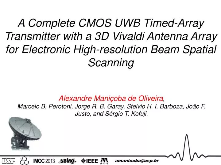
A Complete CMOS UWB Timed-Array Transmitter with a 3D Vivaldi Antenna Array for Electronic High-resolution Beam Spatial Scanning. Alexandre Maniçoba de Oliveira , Marcelo B. Perotoni, Jorge R. B. Garay, Stelvio H. I. Barboza, João F. Justo, and Sérgio T. Kofuji. amanicoba@usp.br. θ t2.

E N D
A Complete CMOS UWB Timed-Array Transmitter with a 3D Vivaldi Antenna Array for Electronic High-resolution Beam Spatial Scanning Alexandre Maniçoba de Oliveira, • Marcelo B. Perotoni, Jorge R. B. Garay, Stelvio H. I. Barboza, João F. Justo, and Sérgio T. Kofuji. amanicoba@usp.br
θt2 θt1 scanned area θt3 ω = Constant where, dθ ω = dt ergo, θ = ωdt ω ω θ dt Traditional Radar System Angle Control more amanicoba@usp.br
Timed-Array TX Radar System Angle Control By Δt d distance(constant) θ c Light speed θ θ Δt c 00 θ1 d scanned area Δt Δt Δtc=dsinθ θ2 Δtiis the delay at antenna i. ergo, Δtc φ x θ= arcsin() d θ Δt1<<Δt2<<Δt3<<Δt4 Δt1< Δt2< Δt3< Δt4 Δt1= Δt2= Δt3= Δt4 d d d y More about PDC More about PG 1 2 3 4 More about pulse more amanicoba@usp.br
Measured results Simulated results more amanicoba@usp.br
SIMULATION RESULTS • Data of some possible Sets and results at 6GHz. amanicoba@usp.br
Conclusions • We proposed a new timed-array UWB transmitter with beamforming capability; • This is controllable beam steering between 17º and -11º for θ angles and between 17º and -18º for φ angles • Maximum gain of 13dB; • New PDC array circuit generate delays digitally controlled from 0 to 63ps; • The pulses obtained with 104mVpp amplitude and 500ps of pulse duration and a power consumption of 543µW, and energy consumption of 0.27pJ per pulse using 2V power supply at PPR of 100MHz; amanicoba@usp.br
Special thanks … • Alexandre Maniçoba de Oliveira would like to acknowledge the material and specs support from Rogers Corporation and User Licence of Microwind 3.5 and support in the review, from Prof. Dr. Etienne Sicard of l'Université de Toulouse.
References A. M. De Oliveira, et al. "A CMOS UWB Pulse Beamforming Transmitter with Vivaldi Array Antenna for Vital Signals Monitoring Applictions” Proceedings of 3rd IEEE Latin American Symposium on Circuits and Systems (LASCAS), 2012, Playa del Carmen. IEEE LASCAS 2012.. EUA : IEEEXplore, p. 1-4, 2012. doi:10.1109/LASCAS.2012.6180337. Zito, D., et al. "SoC CMOS UWB Pulse Radar Sensor for Contactless Respiratory Rate Monitoring". IEEE Transactions on Biomedical Circuits and Systems. Vol. 5. pp. 503-510. Dec. 2011 E. M. Staderini. "UWB Radars in Medicine". IEEE Aerospace and Electronic Systems Magazine, vol 17, pp. 13-18, Aug. 2002. M. Baldi, et al."Analysis and simulation of algorithms for vital signs detection using UWB radars". in: IEEE International Conference on Ultra-Wideband (ICUWB 2011), ISBN: 978-1-4577-1763-5. pp.341-345, 2011.] A. M. De Oliveira. "Conceptual Model of a CMOS UWB Radar transmitter by electronic scanning with Vivaldi array antenna". 2012. 170 pp. Dissertation (Master of Science) - Universidade de São Paulo, São Paulo, 2012. Y. Xiao, C. Li, and J. Lin. "A Portable Noncontact Heartbeat and Respiration Monitoring System Using 5-GHz Radar", IEEE Sensor Journal, vol. 7, no. 7, July 2007, pp. 1042-1043. A. Lazaro, D. Girbau, and R. Villarino, "Analysis of vital signs monitoring using an ir-UWB radar," Progress In Electromagnetics Research, Vol. 100, pp. 265-284, 2010.doi:10.2528/PIER09120302 J. S. Araújo, R. M. S. De Oliveira, and C. L. S. S. Sobrinho. “Novel Technique for Locating an Intruder in 3D Environments by Using a Cooperative System of Multistatic Radars”. Journal of Microwaves, Optoelectronics and Electromagnetic Applications. vol. 10, no. 2 . p. 308 – 322. December 2011. M. Hämäläinem, et al. "On the UWB System Coexistence With GSM900, UMTS/WCDMA, and GPS". IEEE Journal on Selected Areas In Communication. vol. 20, no. 9, pp. 1712 - 1721, December 2002. Microwind v.3.5 Dr. Etienne Sicard, Toulouse, France. Linear Technology Spice (LTSpice) v.4. Linear Technology, Milpitas, CA. Computer Simulation Technology (CST) Microwave Studio (MWS) v.2011, CST of America, Inc., Wellesley MA. T. S. Chu, J. Roderick, and H. Hashemi. "An Integrated Ultra-Wideband Timed Array Receiverin 0.13 um CMOS Using a Path-Sharing True Time Delay Architecture". IEEE Journal Of Solid-State Circuits, vol. 42, no. 12, December 2007. L. Wang, Y. Lian, and C. H, Heng. "3-5 GHz 4-Channel UWB Beamforming Transmitter With 1º Scanning Resolution Through Calibrated Vernier Delay Line in 0.13-um CMOS". IEEE Journal of Solid State Circuits. vol. 47, no. 12, December 2012. Federal Communication Commission, Revision of Part 15 of the Commission’s Rules Regarding Ultra-Wideband Transmission Systems, adopted Feb. 2002, released Apr. 2002. J. M. RABAEY, A. CHANDRAKASAN, B. NIKOLIC. "Digital Integrated Circuits: A Design Perspective" 2nd Ed. Pearson., 2002. 761p. ISBN: 978-01-309-0996-1. G. ZHANG, et al. "Design and implementation of UWB pulse with multiple narrow-band interferences mitigation". Proceedings of Inter. Conf. on Consumer Electronics, Communications and Network (CECNet) 2011. Tianjin: 2011. P. 1154-1157, 2011. ISBN: 978-1-61284-458-9. Doi: 10.1109/CECNET.2011.5769041. H. KIM, et al. "Digital Low-Power CMOS Pulse Generator For Ultra-Wideband Systems". Patent no. US 7715502B2, 7 Set. 2007, 11 Mai. 2010. T. A. Phan, et al.“4.7pJ/pulse 7th Derivative Gaussian Pulse Generator for Impulse Radio”, AUTO-ID Labs at MIT, 2008. H. Kim, D. Park, Y. Joo. “All-digital low-power CMOS pulse generator for UWB system”, Electronics Letters, Vol. 40 no. 24, pp.1534-1535. November 2004. H. Kim, Y. Joo. “Fifthderivative Gaussian pulse generators for subbanded Ultra-Wideband transmitters”, IEEE Trans. Micro. Theory Tech., Vol. 54, no. 4, pp. 1647-1655. April 2006. Y. Zheng, Y. Zhang, and Y. Tong, “A novel wireless interconnect technology using impulse radio for interchip communications”, IEEE Trans. Icro. Theory Tech., Vol. 54, no. 4, pp. 1912-1920, April 2006. T. Kikkawa, et al. “Gaussian monocycle pulse transmitter using 0.18 μm CMOS technology with on-chip integrated antennas for inter-chip UWB communication”, IEEE Journal of Solid-State Circuits, Vol. 43, no. 5, pp. 1303-1312, May 2008. D. D. Barras, et al. “Low-power Ultra-wideband wavelets generator with fast start-up circuit”, IEEE Trans. Micro. Theory Tech., Vol. 54, no. 5, pp. 2138-2145, March 2006. Y. Yang, Y. Wang, and A. E. Fathy. “Design Of Compact Vivaldi Antenna Arrays For UWB See Through Wall Applications”. Progress in Electromagnetics Research, PIER 82, p.401-418, 2008. M. C. Greenberg, L. Virga, and C. L. Hammond, “Performance characteristics of the dual exponentially tapered slot antenna for wireless communication application,” IEEE Trans. On Vehicular Technology, Vol. 52, p.305-310, Mar. 2003. A. Mehdipour, K. Mohammadpour-Aghdam and R. Faraji-Dana. “Complete Dispersion Analysis of Vivaldi Antenna For Ultra Wideband Applications” Progress In Electromagnetics Research, PIER, Vol. 77, p.85-96, 2007. A. Mehdipour, K. Mohammadpour-Aghdam and R. Faraji-Dana. “Complete Dispersion Analysis of Vivaldi Antenna For Ultra Wideband Applications” Progress In Electromagnetics Research, PIER, Vol. 77, p.85-96, 2007.
Contact us. Alexandre Maniçoba de Oliveira, Marcelo B. Perotoni, Jorge R. B. Garay, Stelvio H. I. Barboza, João F. Justo, and Sérgio T. Kofuji. e-mail: {amanicoba, jorge, stelvio, kofuji}@pad.lsi.usp.br; jjusto@lme.usp.br; marcelo.perotoni@ufabc.edu.br (+55 13) 8822-2124 amanicoba@{usp.br; ieee.org; gmail.com; hotmail.com} amanicoba@usp.br
Traditional radar transmitter. amanicoba@usp.br
Traditional radar transmitter. amanicoba@usp.br
Traditional radar transmitter. Beamforming changes the irradiated beam direction electronically, eliminating mechanical systems (BALANIS, 2008; CHU; RODERICK; HASHEMI, 2007; KRAUS, 1997;). Back amanicoba@usp.br
Traditional radar transmitter. Beamforming changes the irradiated beam direction electronically, eliminating mechanical systems (BALANIS, 2008; CHU; RODERICK; HASHEMI, 2007; KRAUS, 1997;). Back amanicoba@usp.br
Timed-Antenna-Array(basicidea) (RIBEIRO, 2012; ZHAO, 2009; KRAUS, 1997; WOLFF, 1966) amanicoba@usp.br
Timed-Antenna-Array(basicidea) amanicoba@usp.br
Timed-Antenna-Array(basicidea) Back amanicoba@usp.br
Timed-Antenna-Array(basicidea) Back amanicoba@usp.br
Proposed Vivaldi antenna: Microstrip Transition line where h and t are the substrate and strip conductor thickness, respectively, and w is the strip conductor width (a). A quasi-TEM analysis is represented (b) (BAHL; TRIVEDI, 1977; WHEELER, 1977) amanicoba@usp.br
Proposed Vivaldi antenna: (DE OLIVEIRA, et al.,2012) (GREENBERG, 2003; MEHDIPOUR; AGHDAM; DANA, 2007; YANG; WANG; FATHY, 2008) amanicoba@usp.br
Proposed Vivaldi antenna: Antennadesigned in CST MW Studio. amanicoba@usp.br
Proposedantennaarray: Dimensions of the Antennas amanicoba@usp.br
Proposedantennaarray: d distance stude: amanicoba@usp.br
Proposedantennaarray: d distance stude: Bad PSI/EPUSP amanicoba@usp.br
Proposedantennaarray: d distance stude: but Volume 200% higher Excellent amanicoba@usp.br
Proposedantennaarray: d distance stude: Volume 108% higher Good amanicoba@usp.br
Proposedantennaarray: d distance stude: d=36.3mm d=58.1mm Back d=72.6mm amanicoba@usp.br
Proposedantennaarray: d distance stude: d=36.3mm d=58.1mm Back d=72.6mm amanicoba@usp.br
ProgrammableDelayController The rocky road to research growth... First-orderRC network.(RABAEY; CHANDRAKASAN; NIKOLIC, 2002). System channelofproposedtimed-arraytransmitter. Static inverter (a) being its symbol (b) electrical diagram with two complementary transistors and the output node capacitance (capacitance load or CL) and key model of the dynamic behavior of the static inverter with Vin = 0 (C ) and Vin = Vdd in (d)(RABAEY; CHANDRAKASAN; NIKOLIC, 2002). amanicoba@usp.br
ProgrammableDelayController The rocky road to research growth... Static inverter (a) being its symbol (b) electrical diagram with two complementary transistors and the output node capacitance (capacitance load or CL) and key model of the dynamic behavior of the static inverter with Vin = 0 (C ) and Vin = Vdd in (d)(RABAEY; CHANDRAKASAN; NIKOLIC, 2002). System channelofproposedtimed-arraytransmitter. Diagram of a basic element of delay formed by the static inverter. (a) Setting time by varying the resistance, (b) capacitance and (c) both. amanicoba@usp.br
ProgrammableDelayController The rocky road to research growth... Delay element formed by two inverters connected in series (a). Illustration of the waveforms at nodes Vin, Vlinha and Vout (b). System channelofproposedtimed-arraytransmitter. By (RABAEY; CHANDRAKASAN; NIKOLIC, 2002) amanicoba@usp.br
ProgrammableDelayController The rocky road to research growth... IEEE LASCAS 2012 PDC with variable capacitance a Vlinha node (De Oliveira et al., 2012). IEEE IMOC 2013 System channelofproposedtimed-arraytransmitter. PDC with n-channel resistance variable. amanicoba@usp.br
ProgrammableDelayController The rocky road to research growth... System channelofproposedtimed-arraytransmitter. amanicoba@usp.br
ProgrammableDelayController The rocky road to research growth... Back amanicoba@usp.br
ProgrammableDelayController The rocky road to research growth... Back amanicoba@usp.br
Pulse Generator no matching KIM, et al., 2004 Theoretical 5th Deriv. Gaussian Pulse (KIM, et al., 2004; TUAN et al., 2007; XIE et al., 2008) amanicoba@usp.br
Pulse Generator no matching Theoretical 5th Deriv. Gaussian Pulse (KIM, et al., 2004; TUAN et al., 2007; XIE et al., 2008) amanicoba@usp.br
Pulse Generator Newproposedtopology: amanicoba@usp.br
Pulse Generator Newproposedtopology: The proposed 5th derivative Gaussian PG: (a) general structure of the PG; (b) Simplified time diagram; (c) PG proposed in [16, 17]; (d) AND gate formed by a CMOS NAND gate and a static inverter; (e) Static inverter circuit; and (f) three inverter –delay circuit. amanicoba@usp.br
Pulse Generator Newproposedtopology: amanicoba@usp.br
Pulse Generator Newproposedtopology: amanicoba@usp.br
Pulse Generator Newproposedtopology: SUMMARY OF THE SIMULATED PULSE GENERATOR PERFORMANCE. amanicoba@usp.br
Pulse Generator Newproposedtopology: PERFORMANCE AND COMPARASION OF UWB TRANSMITTER. Back amanicoba@usp.br
Pulse Generator Newproposedtopology: PERFORMANCE AND COMPARASION OF UWB TRANSMITTER. Back amanicoba@usp.br
The pulse choice dBm/MHz Sinc Pulse dBm/MHz Gaussian Pulse dBm/MHz Square Pulse (WENTZLOFF,2007) Time Frequency amanicoba@usp.br
The pulse choice • The Gaussian pulse has a DC component that makes the less radiation efficiently. (ZHUANG, W., SHEN, X.; BI, Q., 2003; TOYA et al., 2011; DE OLIVEIRA, 2012B). dBm/MHz Gaussian Pulse Frequency Time (SHENG et al., 2003; ORNDORFF, 2004). amanicoba@usp.br
The pulse choice • Toya et al. (2011), De Oliveira et al. (2012) as well as several other studies (egZhuang, W.; Shen, X.; Bi, Q., 2003; Kim, H. et al., 2010;) have used a derivative Gaussian pulse, which isn´t present DC component and has a circuit complexity degree related directly to the derivative degree. Derivation degree Circuit complexity degree amanicoba@usp.br
The pulse choice dBm/MHz FCC indoor mask FCC outdoor mask 5th Gaussian derivative order Frequency in GHz Derivation degree Circuit complexity degree Back amanicoba@usp.br